 Colin Alston
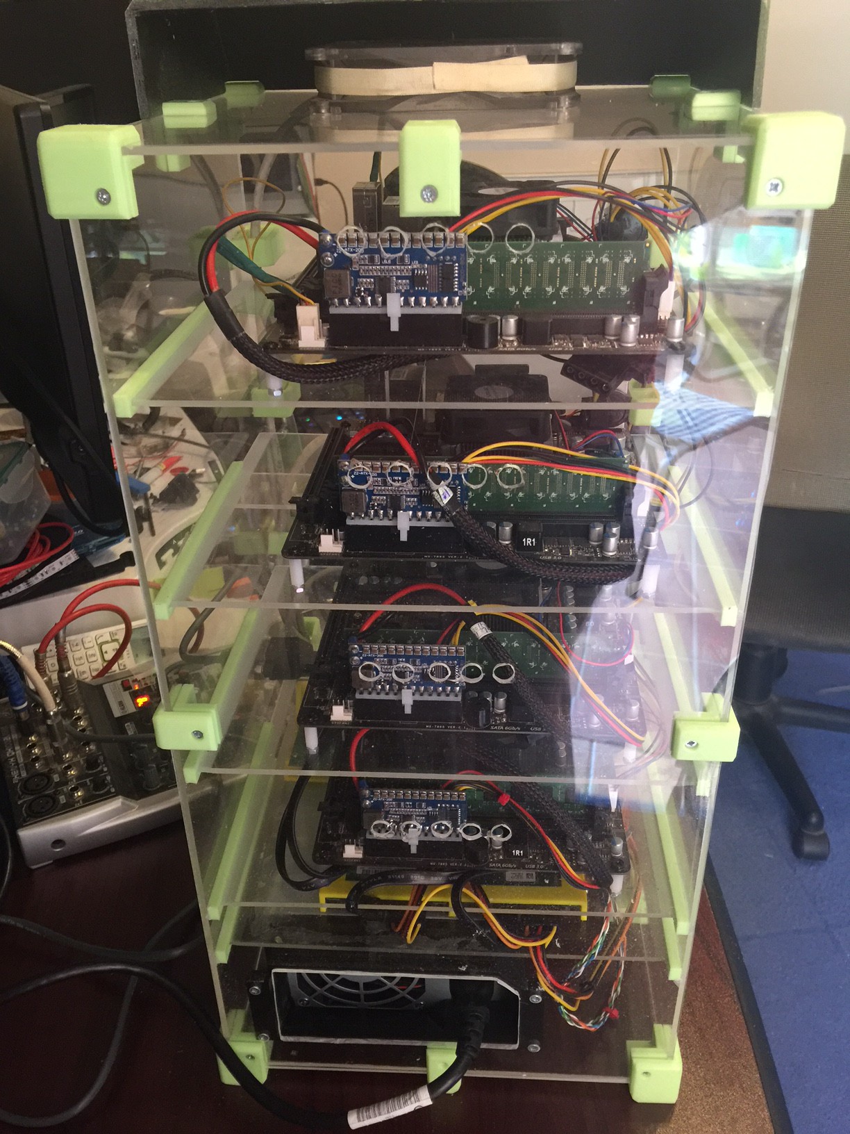
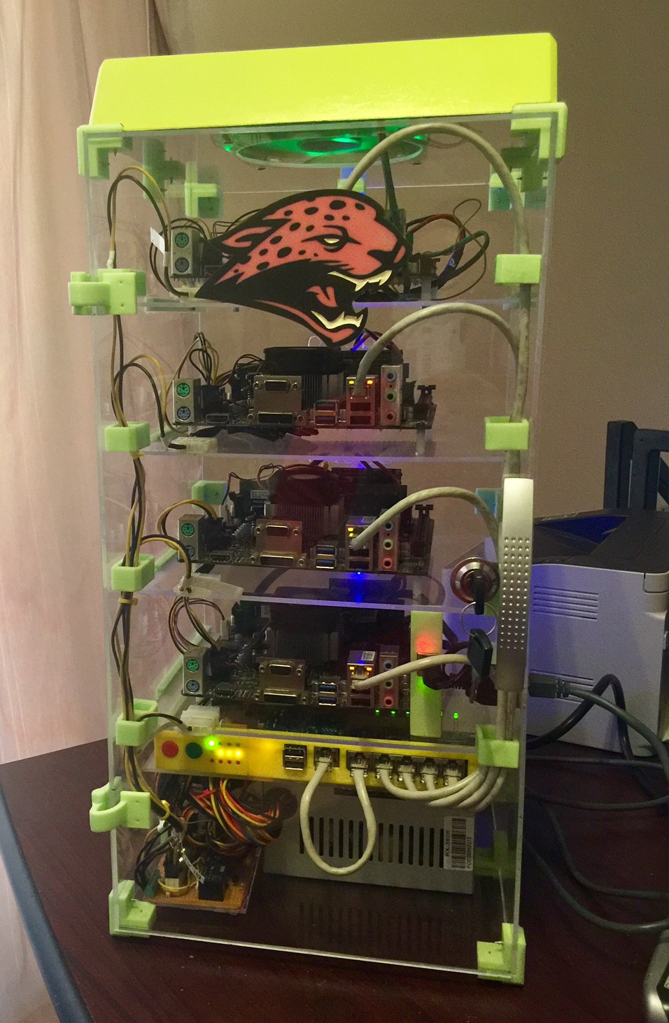
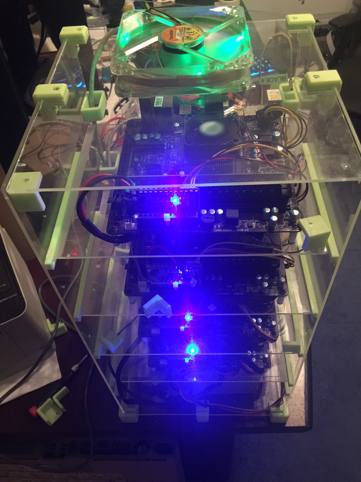
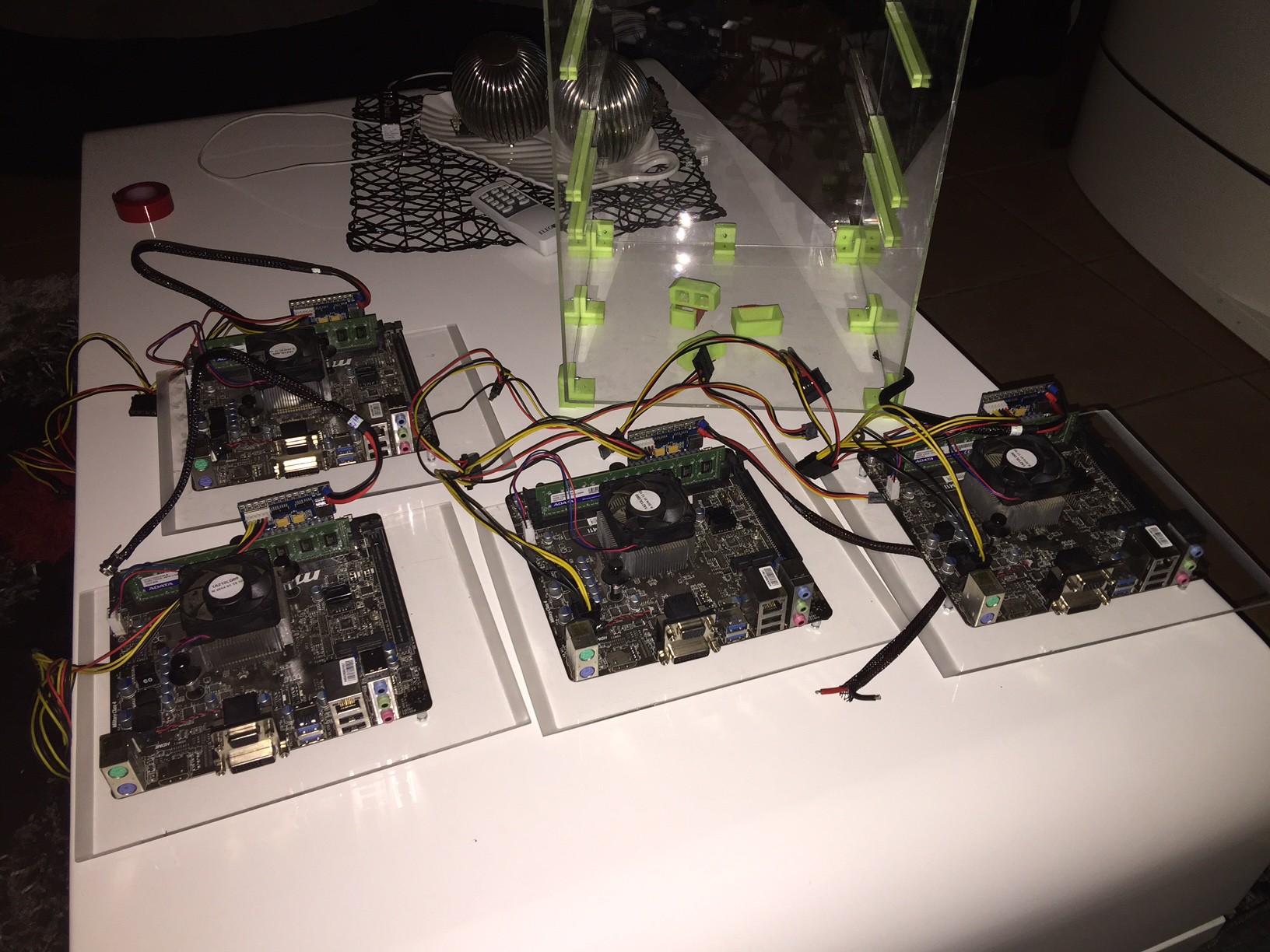
For some time I'd been thinking about building my own little supercomputer to use as a test bed for software I use at work like Elasticsearch and Ceph, and then also earn about the more esoteric work of HPC with MPI and funny interconnects. I came across someone selling some populated MiniITX boards with AMD Jaguar architecture chips on them, with 2GB of memory included they were around the same price as a RaspberryPi - only infinitely more flexible. For starters a Pi only has 1GB of memory, and you're stuck with that - which is annoyingly too little for running anything serious. The other more significant problem is the lack of gigabit ethernet on the Pi's. SATA is also nice to have, although the compute nodes have no disk at all attached - they boot and run entirely from LAN.
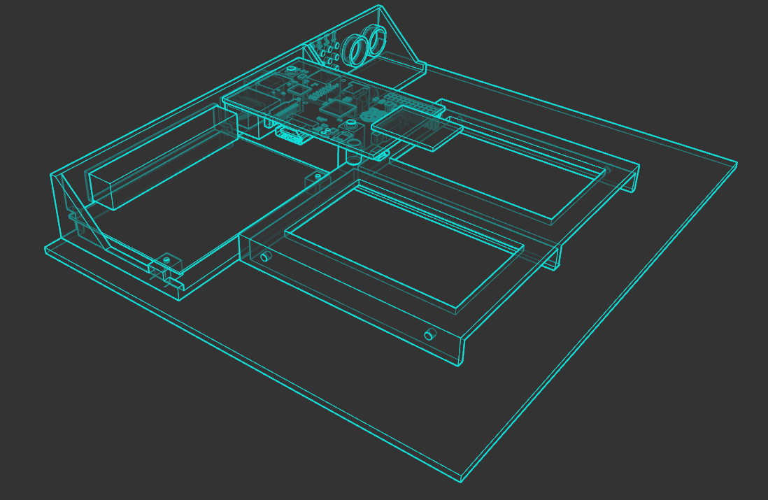
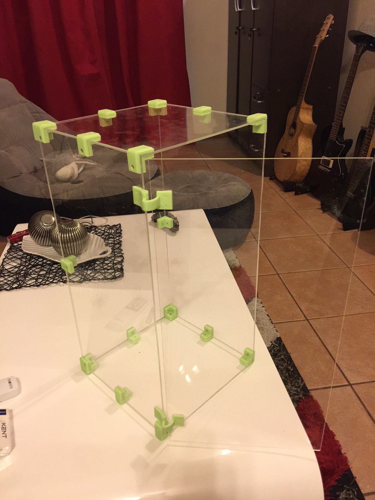
And so I embarked on building the TinyJaguar, named in part for the CPU architecture, and its idol the Oak Ridge Jaguar... which it has absolutely no parts in common with

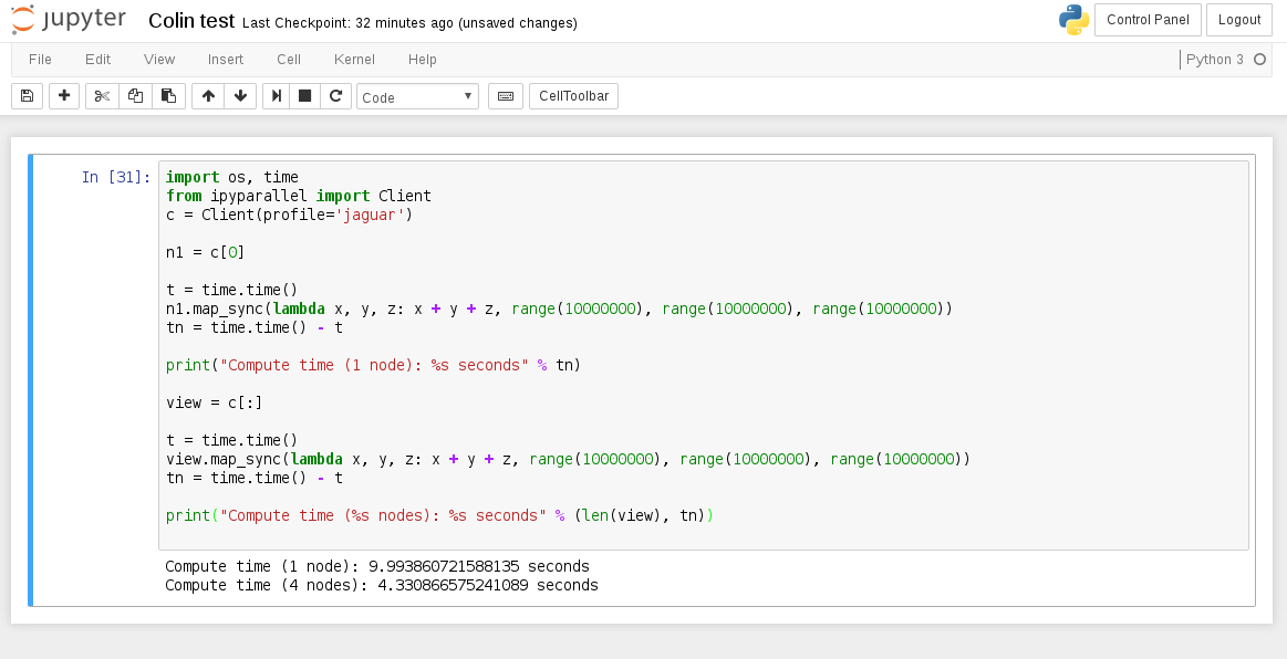 This is one of the basic examples from ipyparallel docs that I just knocked up a notch in iterations because obviously at small iterations the performance hit from reducing the computation results from the nodes over GigE stuff is actually slower over multiple nodes. This is quite a good reflection of Amdahl's Law in the perils of parallel workloads, you don't always get a performance increase over multiple compute nodes, and you almost never get a linear performance increase by adding more nodes. This is why Cray's and what-not have ridiculously expensive high bandwidth connections between computing cores to overcome the latency bottleneck, and also why wiring code for an HPC is not so easy as for a single system.


 Retroplayer
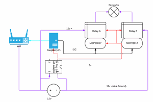
 Aleks Clark
 Ryan Walmsley
 Saul Cozens
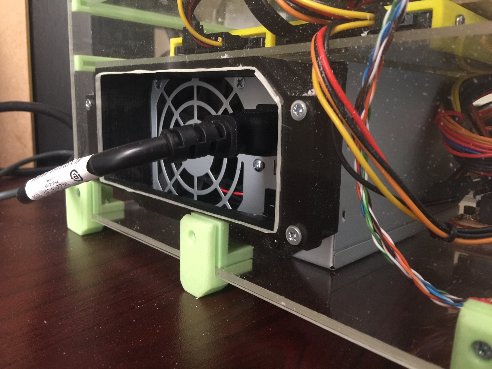
Any information on getting one power supply to power multiple ITX motherboards?