 Colin Alston
The schematic for the management module circuit looks somewhat complicated but it's really just a lot of painful wiring.
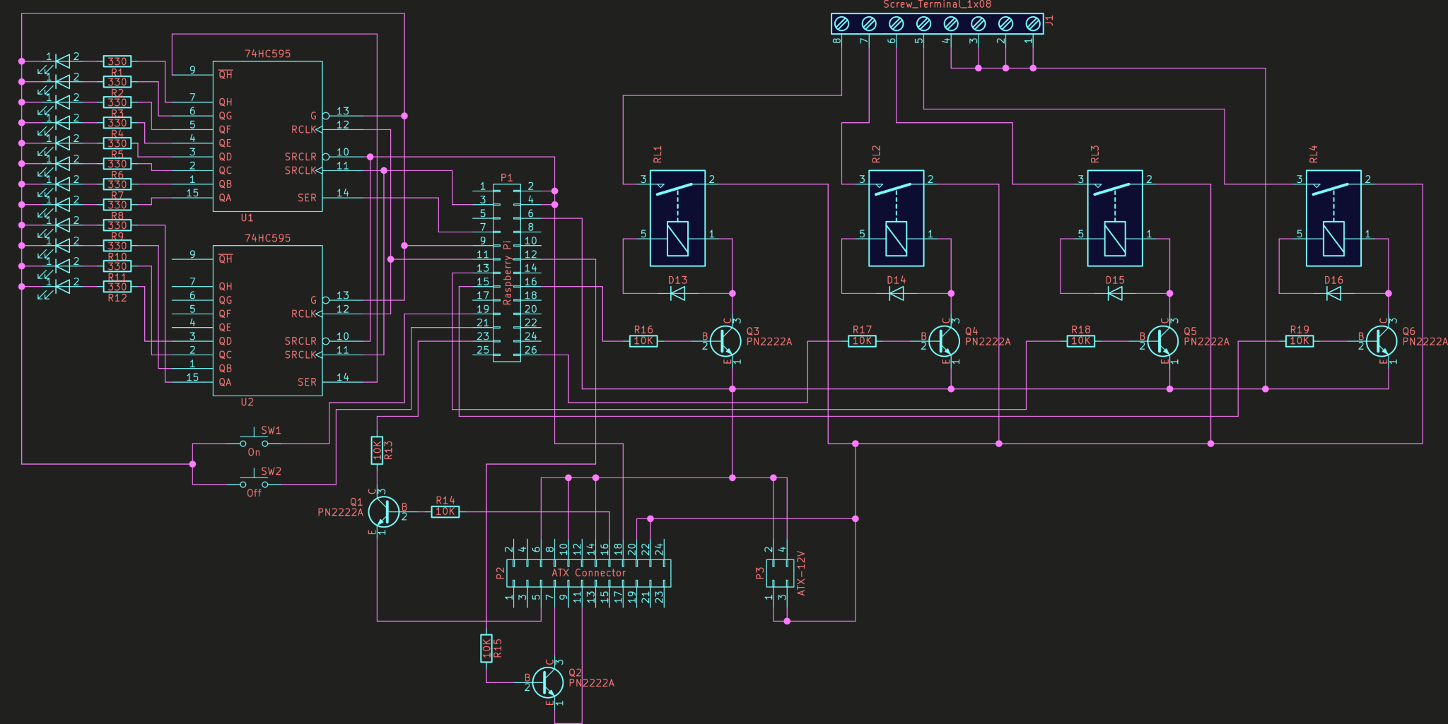
The gist of the functionality lies in implementing the ATX standard, which is simply dropping the PS ON (green wire) to ground, and then waiting for Power Good (grey) to go high. If you actually care about your Raspberry Pi then it would be a good idea to isolate those signals with optocouplers rather than transistors. The 5V standby line on my power supply provides more than enough power for the Raspberry Pi. I also went for 12V relays because I had a bunch of those lying around but using 5V relays would also work just be sure to connect them to the 5V supply obviously (not the standby supply).
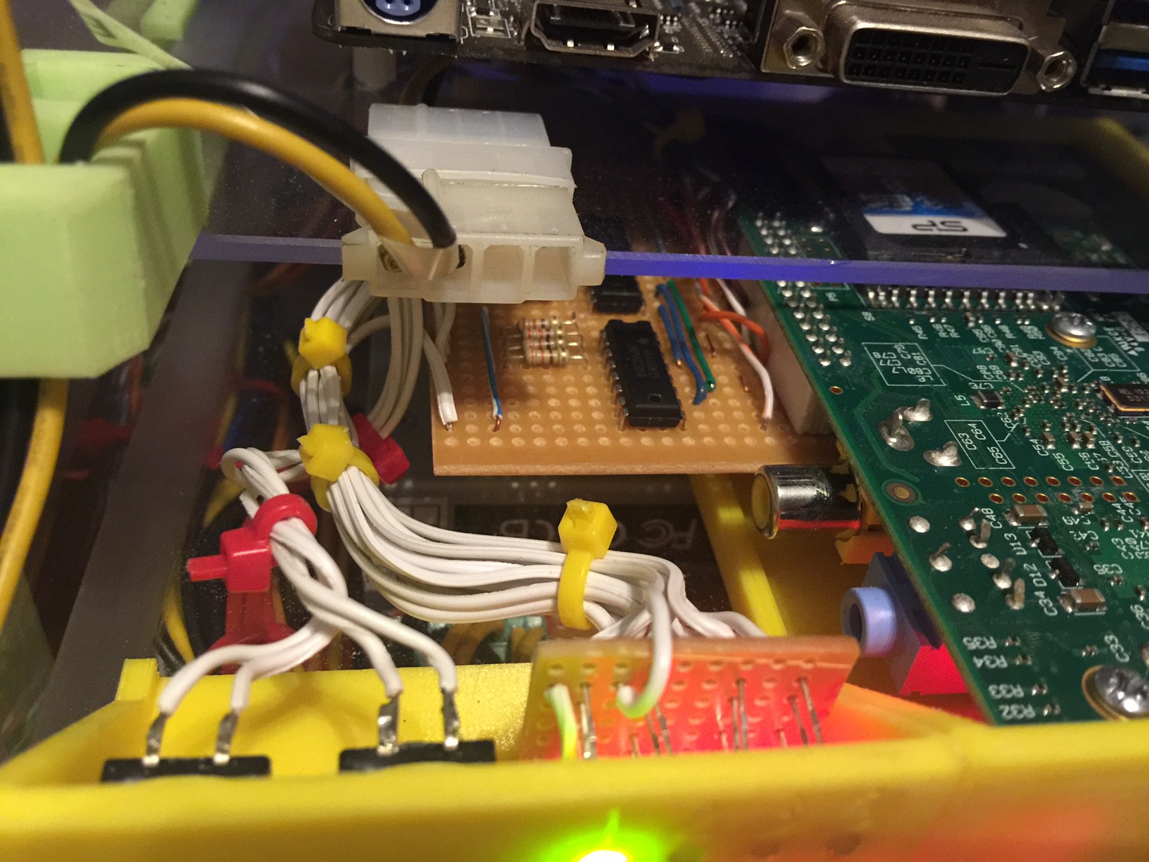
I had a bit of a difficult time locating new ATX PCB connectors somewhere quick and local, except RS who rip us off in developing countries. Molex call these things 24 pin Mini-Fit Jr connectors, but I also made use of the extended 12V supply to ensure a better current rating to my nodes. In the end I desoldered the connectors from an old water damaged motherboard I had in my junk pile.
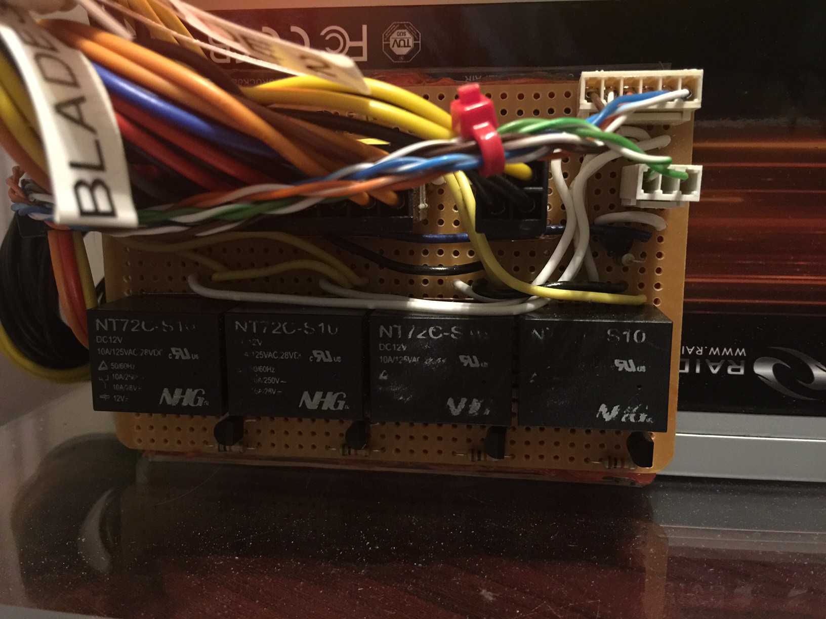
I wired up the schematic using some cheap and easy strip board because I'm bad at laying out PCB's and wanted to see if it worked first. I also split the controller into two parts, with one board handling the status LEDs and buttons and another handling the power supply. The two are connected using some CAT5 cable and SIL connectors.
Discussions
Become a Hackaday.io Member
Create an account to leave a comment. Already have an account? Log In.