 Simon
Simon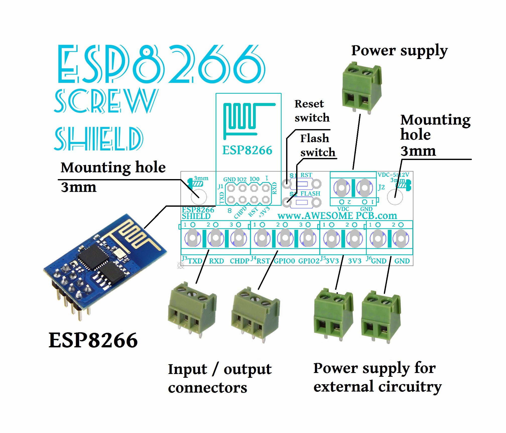
UPDATE 2
There are few things which has ESP8266 Wi-Fi - SCREW SHIELD
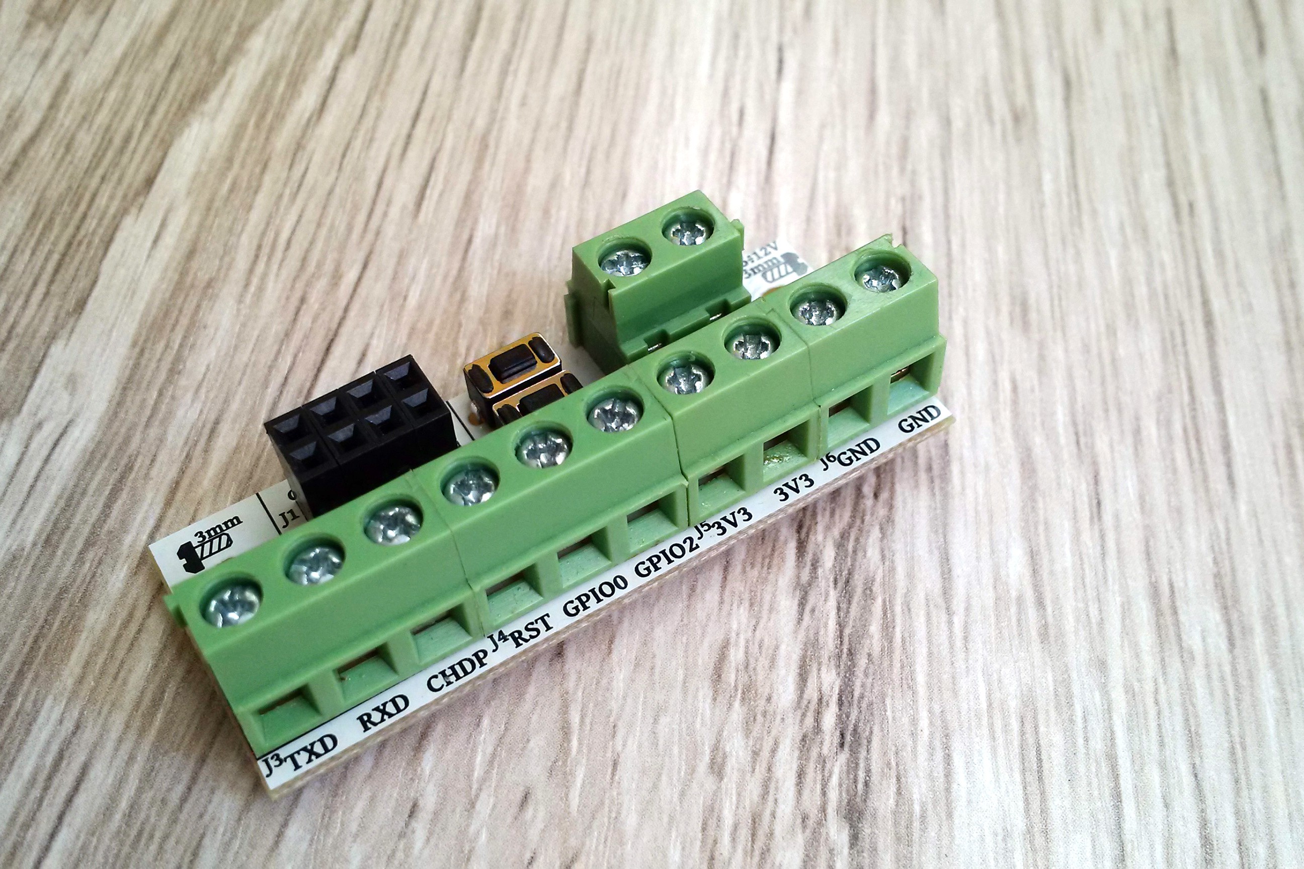
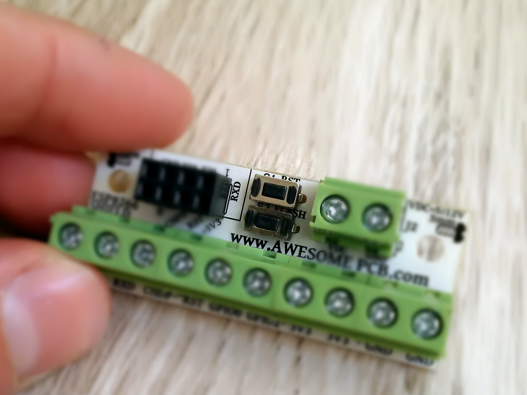
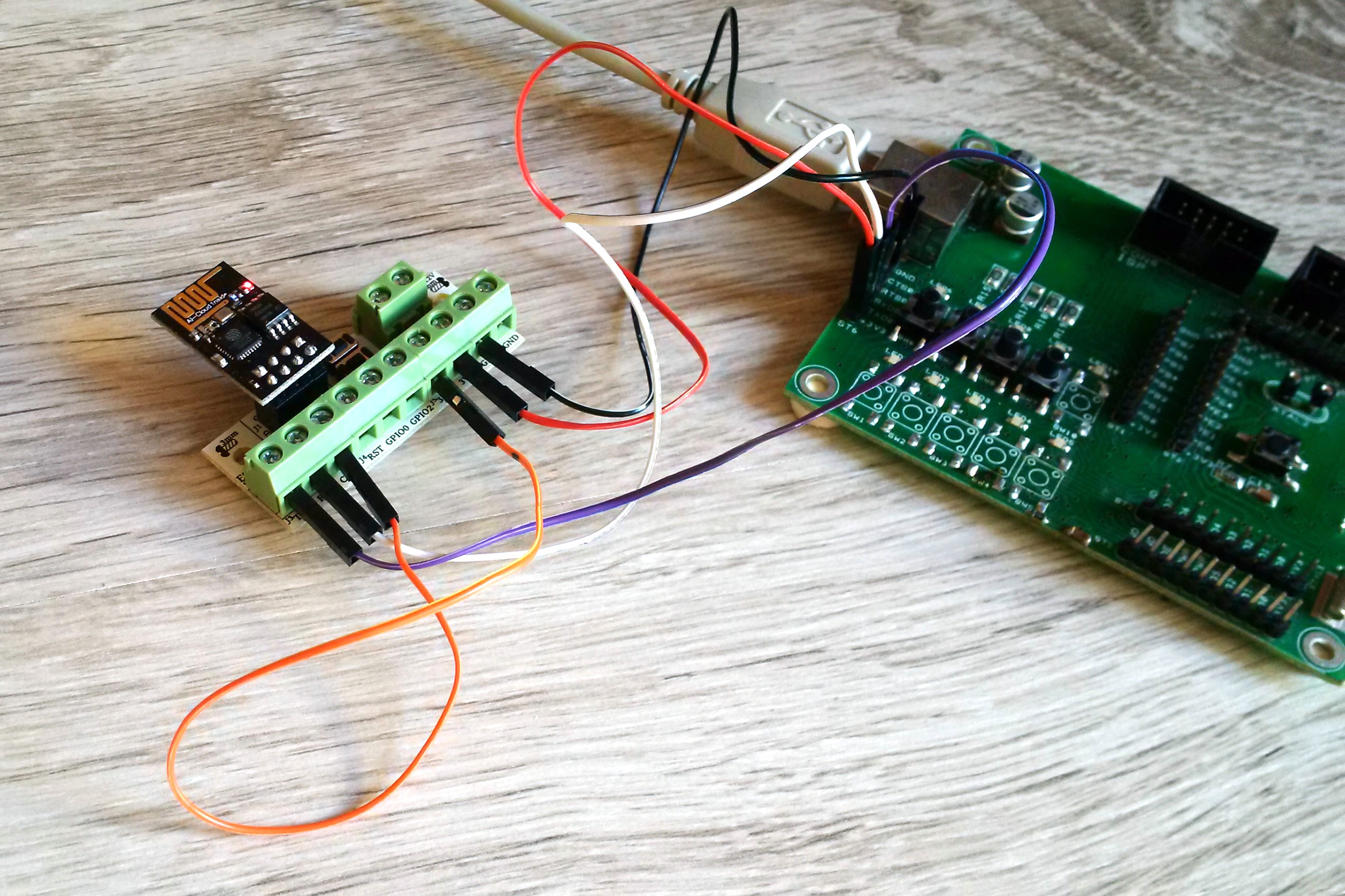
Screw connectors that allowed you realy fast and simple addapt ESP8266-01 in the field. Basicly you need to have just a screwdriver and that is all, no soldering required. Just screw cable to connectors and you are ready to go with your device.
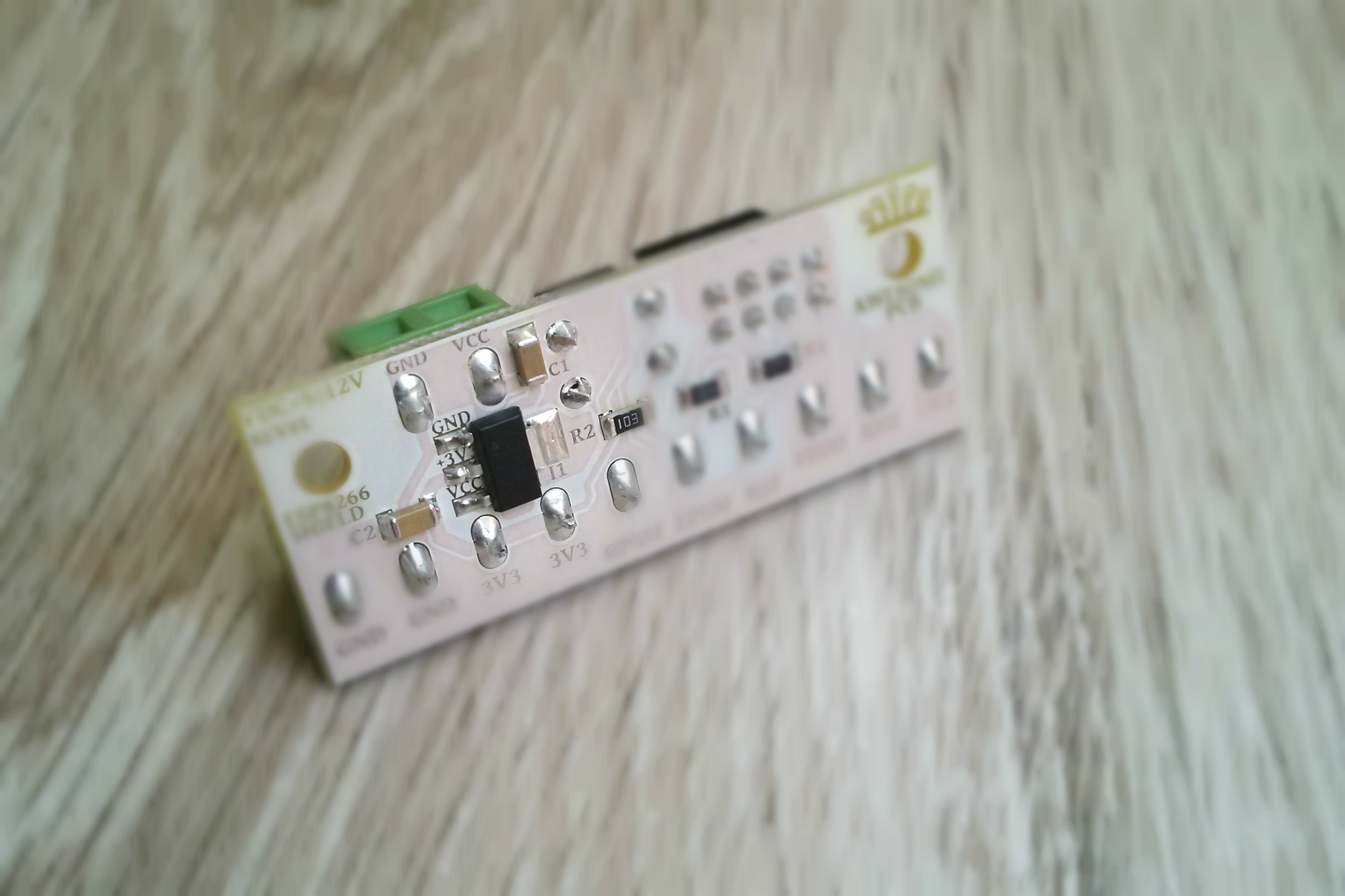
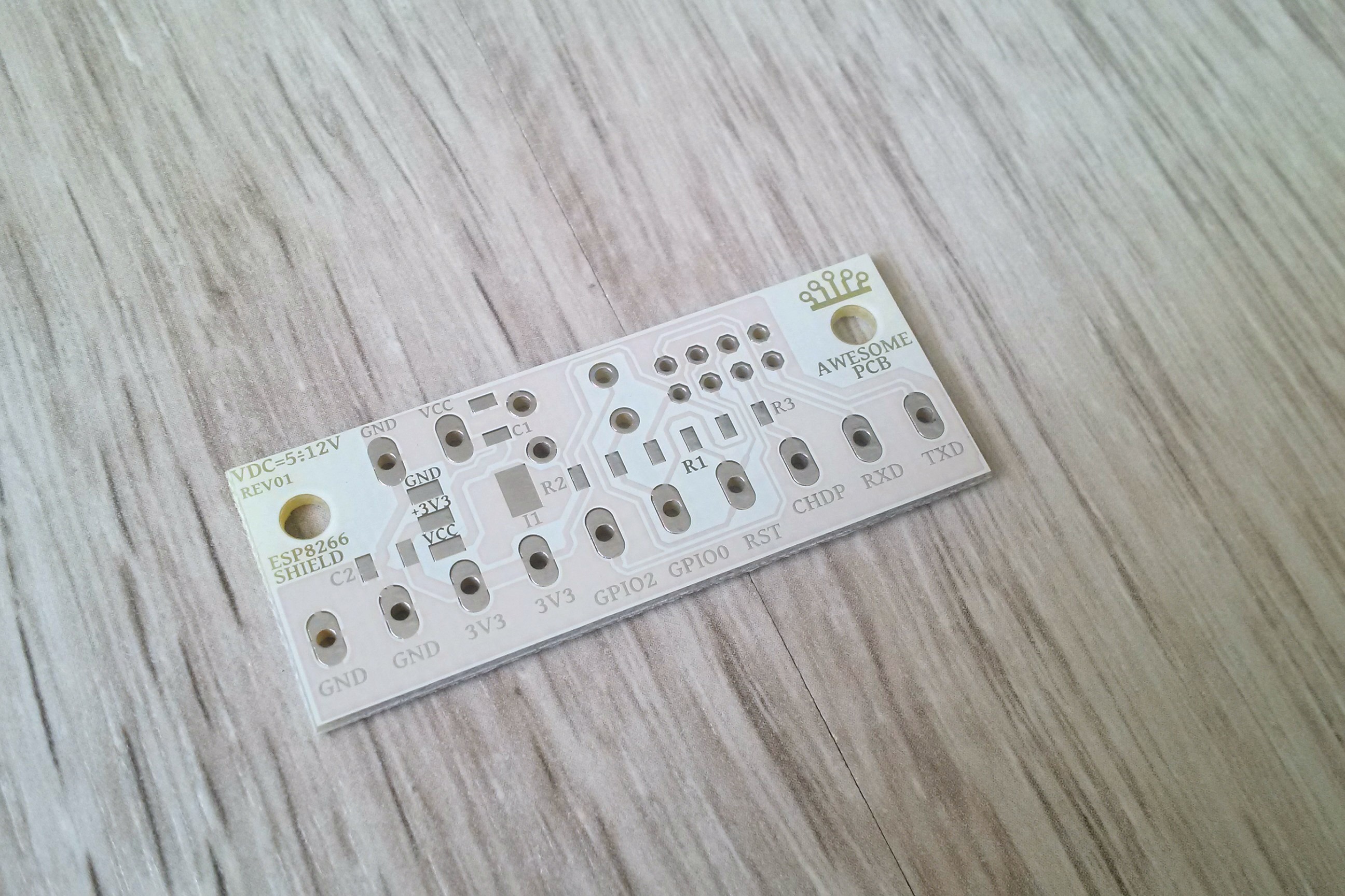
ESP8266 Wi-Fi - SCREW SHIELD has build in power supply stabilizer. As you may notice ESP8266 works with 3.3V logic as well power supply. On shield you will find dedicated connector to connect external power supply from the range of 5÷12VDC.
Output current of power supply is 800mA. Because of this you can supply ESP8266 and any other circuitry in your system.
There are 2 screw holes 3.3mm diameter on PCB. This allowed you basically adapt your ESP8266 anywhere.
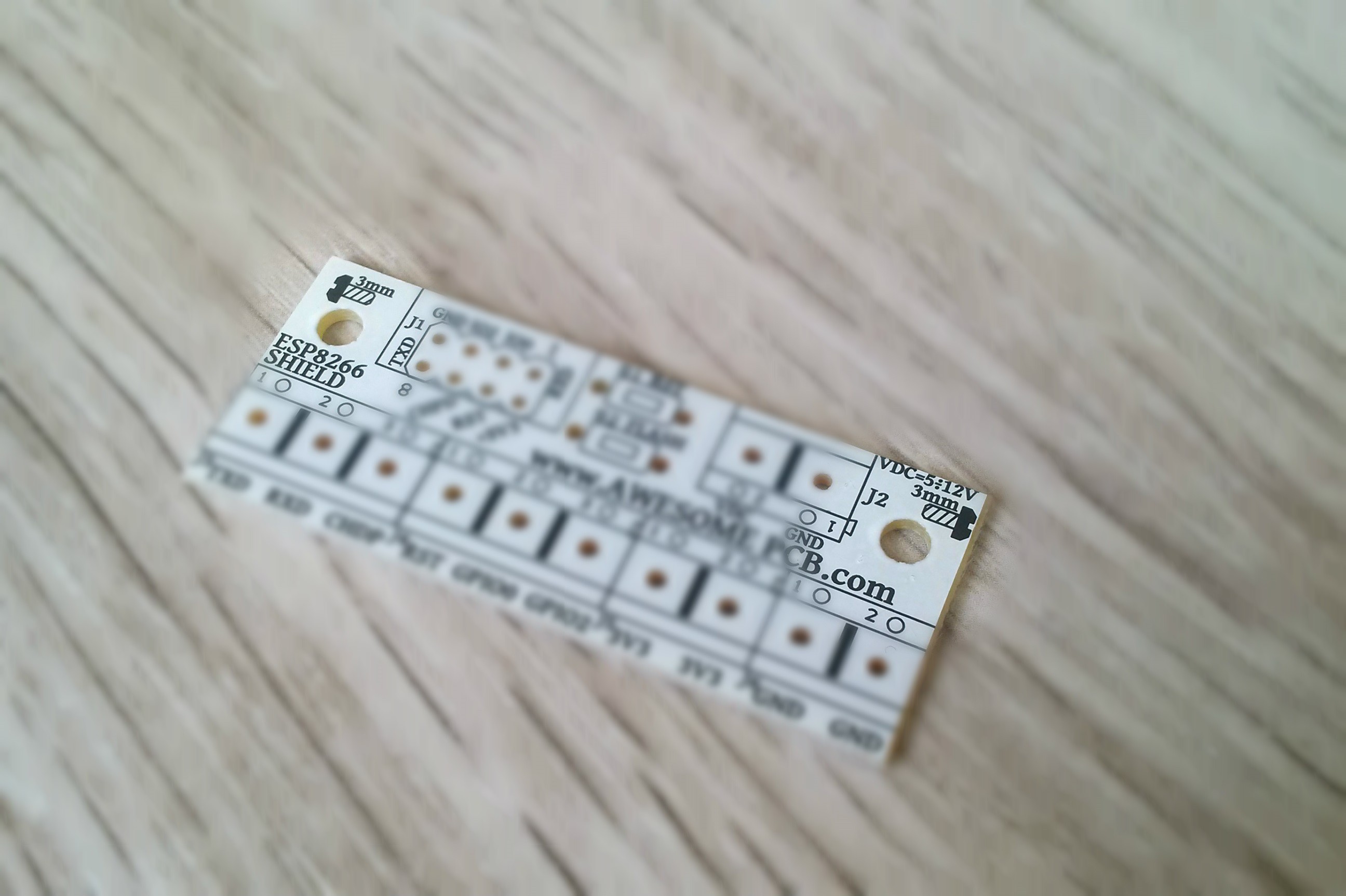
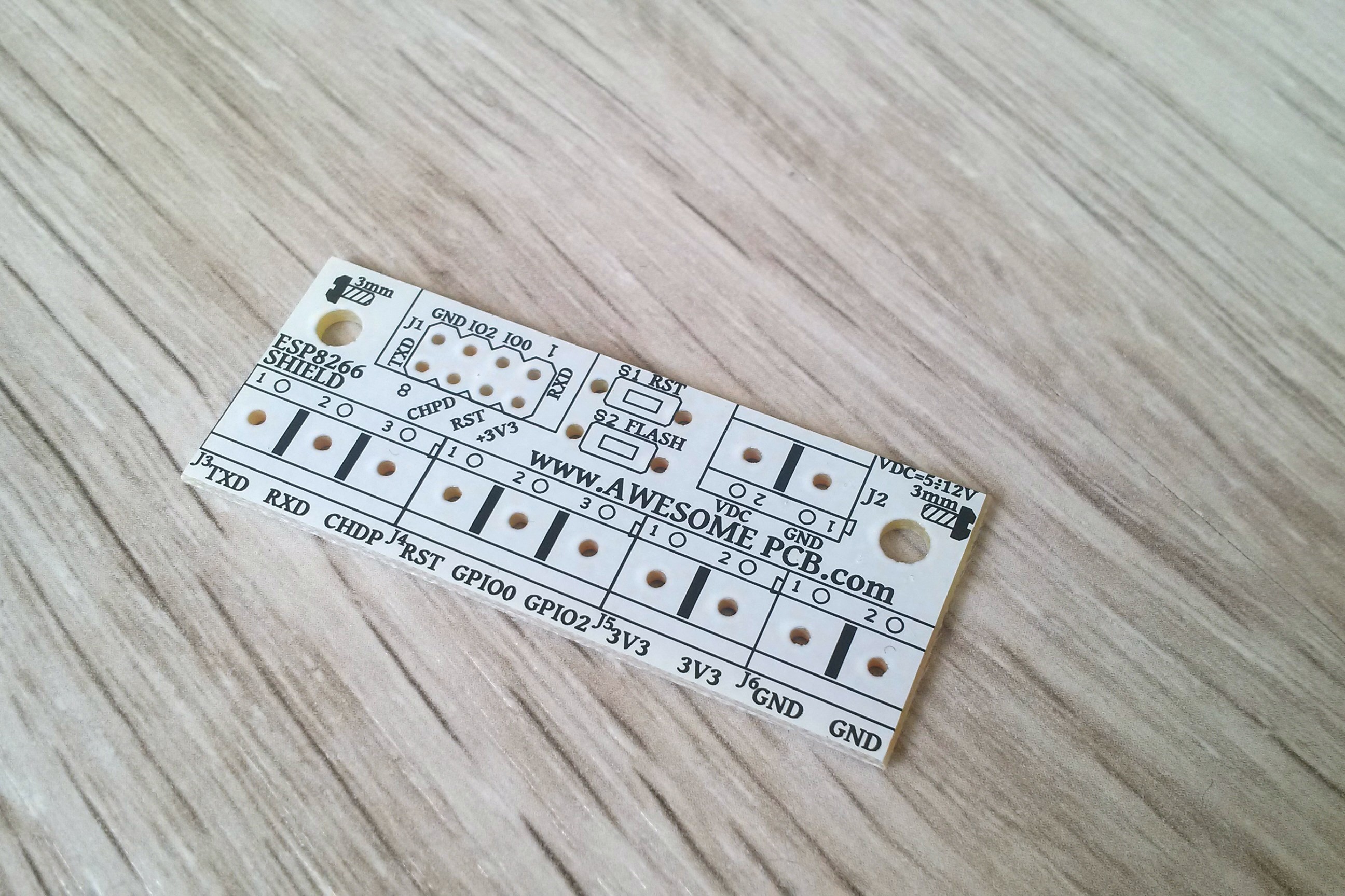
On the SCREW SHIELD PCB you will find full description of pins on top and bottom side. This simplified and speed up assembly in your system without looking in the the documentation of ESP8266-01.
On the PCB there is a reset switch which allows you any time reset ESP8266.
Flash switch provide ability to upgrade a firmware on ESP8266.
UPDATE 1
By the advice danjovic i add 2 switches to the shield.
S1 - this is the reset switch, to make a hardware reset of ESP8266
S2 - this is the button for flash of ESP8266
A this moment this shield have acces for all of the ESP8266-05 pins which can be screw by cable to outside world.
Shield and ESP8266 can be supplied from external power source by low drop stabilizer +3V3 on the output.
In addition we have also 2 slots for +3V3 and 2 slots for GND for external circutry.
On the board we have also 2 mounting holes with 3 mm diameter.
All of the pins are well describe to simplify to maximum usage proces without looking in to the specification.
If you will find an idea what to add to this board or how to improve it feel free to make a comment.


 ElectroBoy
 Ivan Stepaniuk
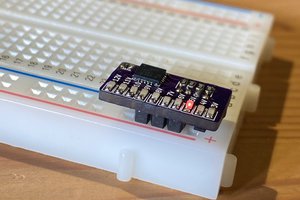
 OzQube
Interesting! Consider adding the pullup resistors and solder jumps to make easier to configure the board.