0%
0%
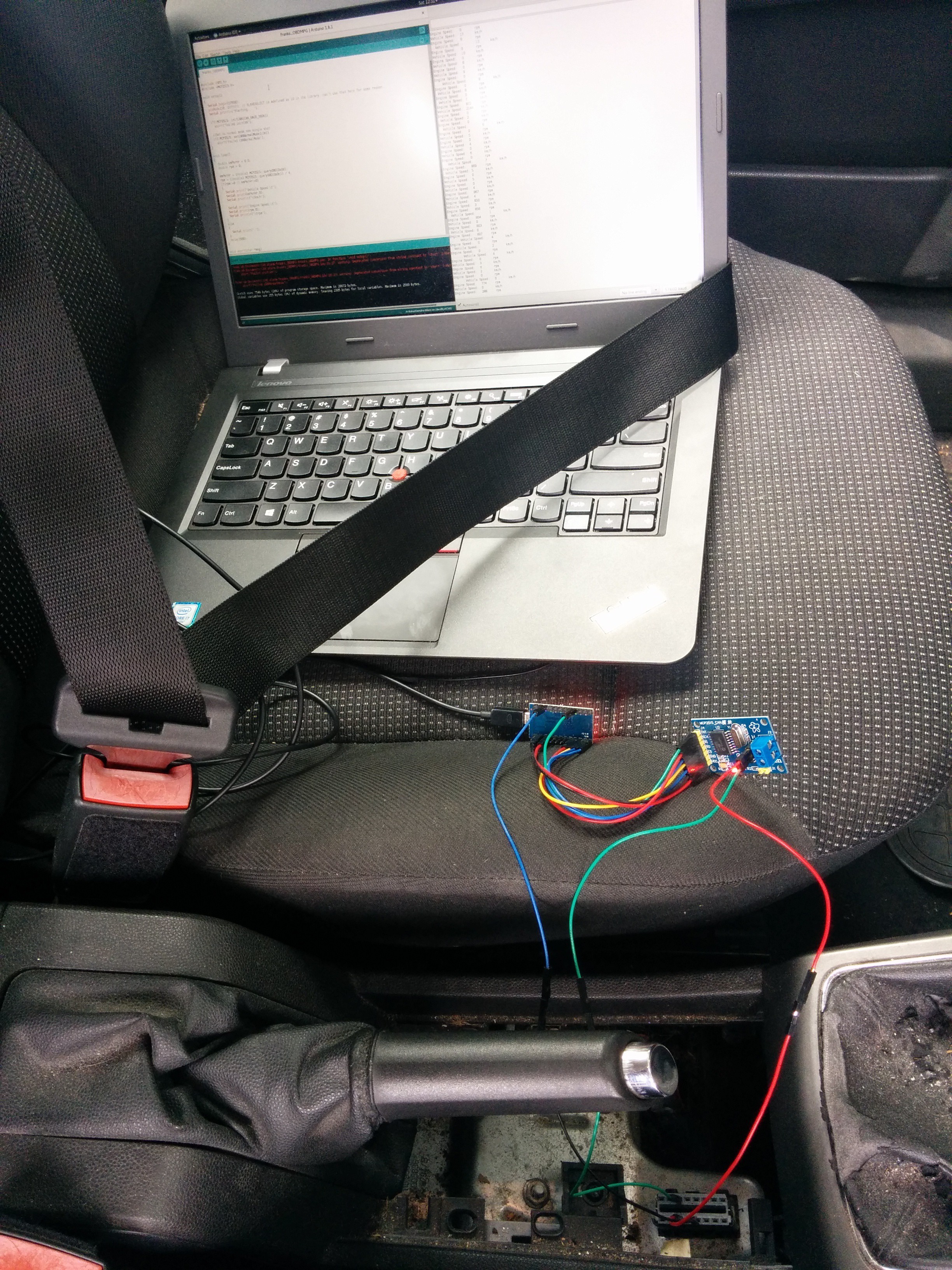
Audible CAN-bus alarm
Monitor vehicle signals and beep when something's wrong
 Andrew Bolin
Become a Hackaday.io member
Already have an account? Log in.
Just one more thing
To make the experience fit your profile, pick a username and tell us what interests you.
Pick an awesome username
hackaday.io/
Your profile's URL: hackaday.io/username. Max 25 alphanumeric characters.
Pick a few interests
Projects that share your interests
People that share your interests

 matthew
 [skaarj]
 Julian Costas
 Mike Thielvoldt
Hi Andrew,
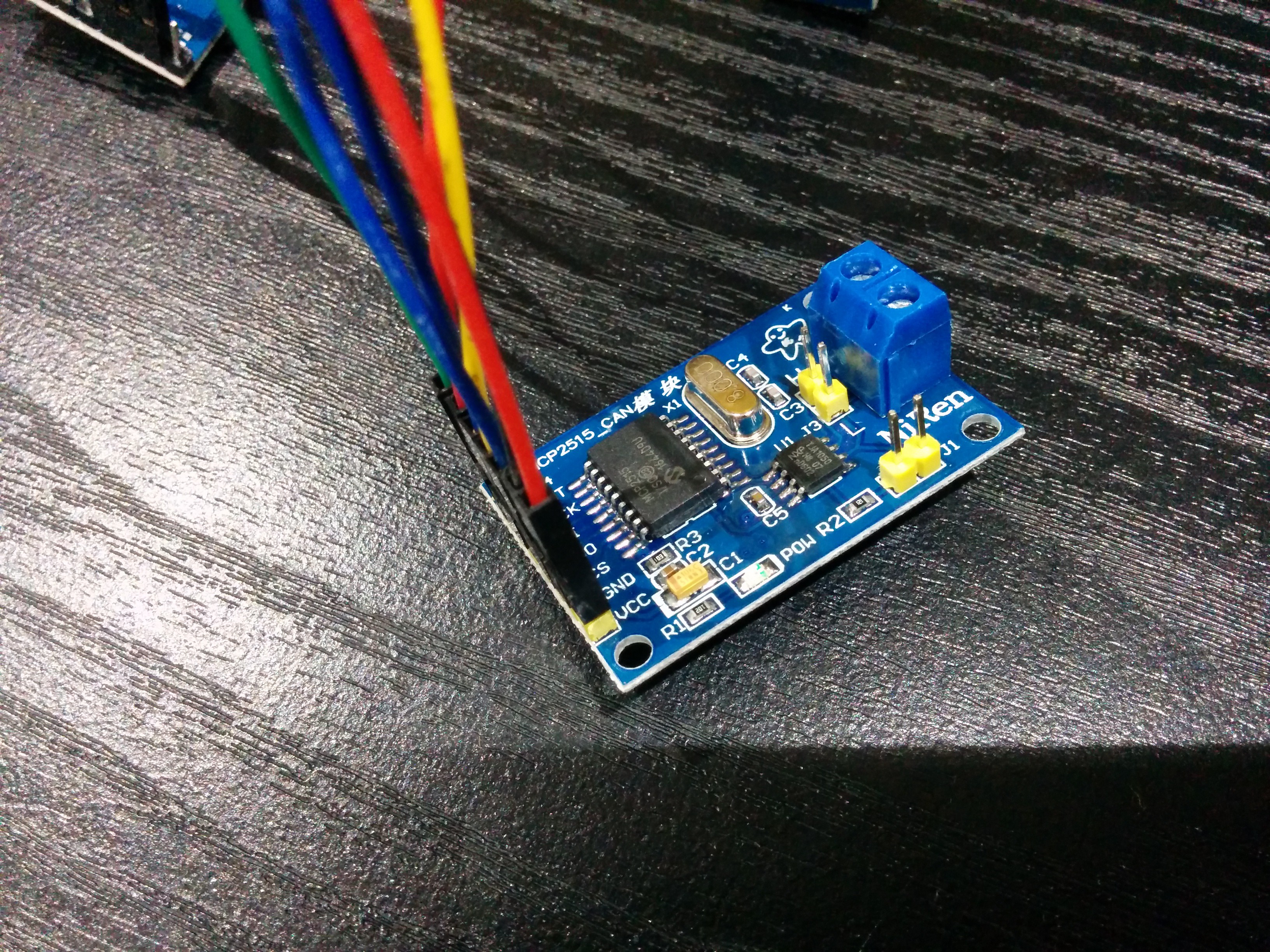
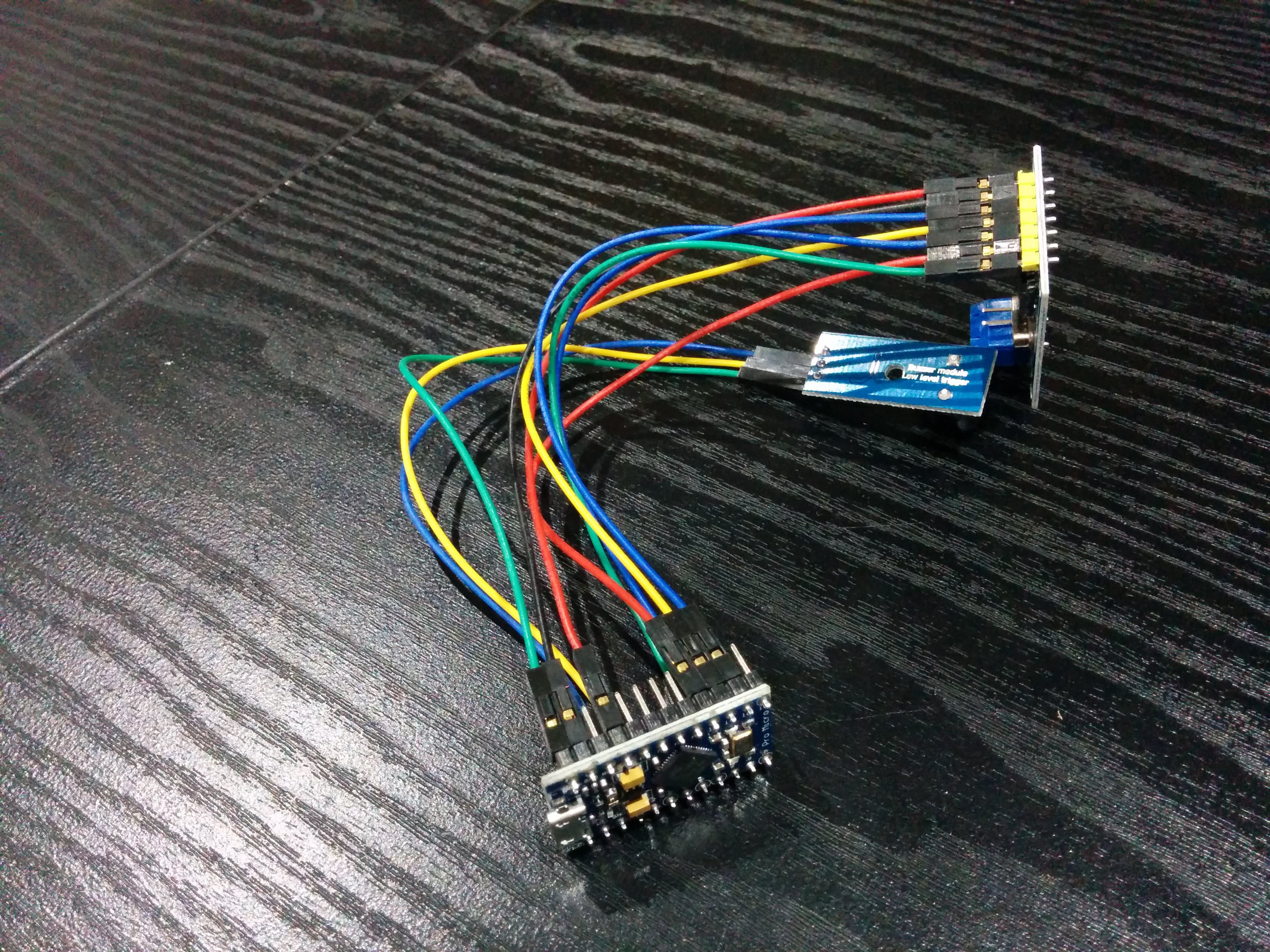
May I ask how do you initialize the can module with Pro Micro?
I mean there is no dedicated MISO/MOSI/INT etc pins. How do you configure them?