 Noah Thurston
As of about two weeks ago, I've had some basic tests for nRF24L01 and the Arduino pro mini completed.
The goals of this test: Be able to turn on and off two synced LEDs on two separate microcontrollers with the press of one button.
This involved:
- Transmitting and receiving with the nRF24L01 transceivers
- Controlling these transceivers with Arduino pro minis
- Writing C++ with the RF24 library (TMRh20 fork)
- Supplying power (preferably battery) to 5V Arduino and the 3.3V nRF
Below is one of the two devices made for this test (the other one is built with the same design on a bigger breadboard)
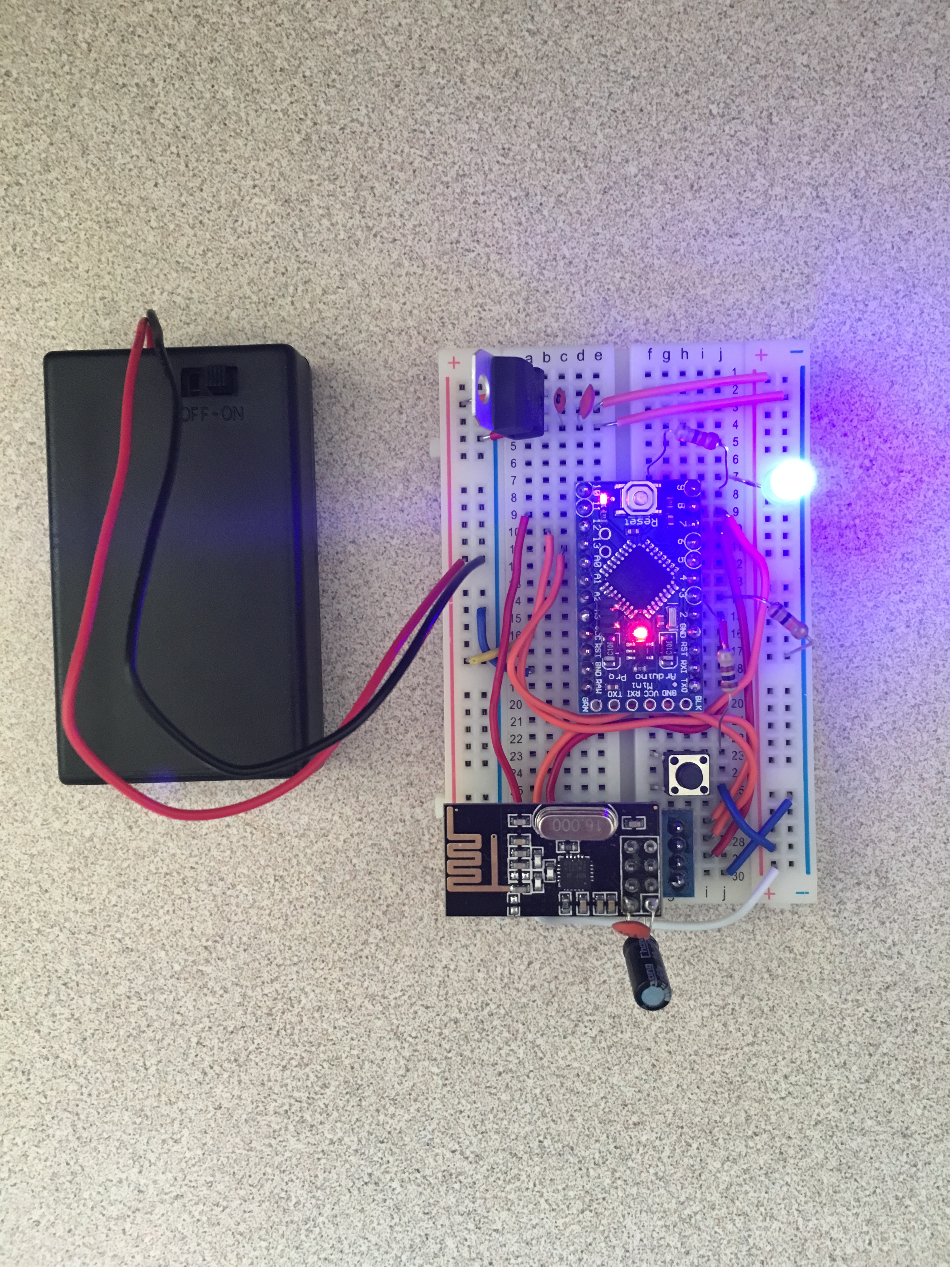
The main part of this circuit is the Arduino pro mini shown in the center. I chose this microcontroller because it was well supported by the RF24 library and very cheap (~$3 a piece). I wrote the code for it with the RF24 "getting_started" sketch as reference, and you can find both on my linked GitHub repo.
Towards the bottom of the breadboard you can see the black nRF24L01 module, with the small trace antenna. I chose these modules because they are also very, very cheap (~$1 a piece), relatively low power since they draw about 20mA at 3.3V and easy to interface over an SPI bus. You can see attached to this modules on the DIP pins are two capacitors; a 0.1uF ceramic disc capacitor and a 10uF electrolytic capacitor. These are attached parallel to Vcc and ground to act as bypass resistors and smooth the power supply for the nRFs, who are known to have faulty performance without a good power supply.
Also shown is the lit LED on the top right and black pushbutton on the bottom right. The button is connected to an arduino io pin, and is normally open with a pull down resistor to keep the state from floating. The LED is also connected to an arduino io pin.
Finally in the top left is a 3.3V regulator, and to the left is a battery pack. There is a lot to talk about when it comes to powering this project, and I plan on doing a separate build log on power alone, so I'm going to be brief here. The battery pack contains 3 AAA batteries for a 4.5V supply. The arduino should be supplied 5V but, it seems like 4.5V is within its tolerance for something this lower power. And since the arduino has an on board power regulator, I was able to connect the battery pack leads directly to the arduino Vcc and GND. The 3.3V regulator at the top is a LM33, part of the 1117 series, and is for the nRF. It has a dropout voltage of 1.2V which means for it to produce a Vout of 3.3V the Vin must be +4.5V, so this AAA battery pack is just barely cutting it, but regardless it still seems to be working.
(a video of the working devices can be found on the linked GitHub in the "pictures-videos" directory)
After debugging the code a little bit, everything worked well. When the button was pushed on one, both LEDs lit up immediately with no perceivable lag. The range, when the PA level was set to the highest possible was upwards of 40 meters in open air but it struggled to get through any barrier thicker than a couple inches. Ultimately the test was a success; my code and the library worked on the arduino, the nRF was responsive when transmitting and receiving, and the battery pack power was enough for both the microcontroller and the arduino.
Discussions
Become a Hackaday.io Member
Create an account to leave a comment. Already have an account? Log In.