Close
0%
0%

Project Precision

Digital Handed Clock

Similar projects worth following
This is a handed clock, but you can't really call it analog, since nothing on it actually moves. All of the hands are composed of rings of LEDs, each one of which is either on or off, so it is a digital handed clock. This clock has an hour hand, a minute hand, a second hand, and a third hand. Features a Charlieplex with 240(!) LEDs, and uses a GPS to make sure that the time is accurate enough to justify the precision at which it is displayed.

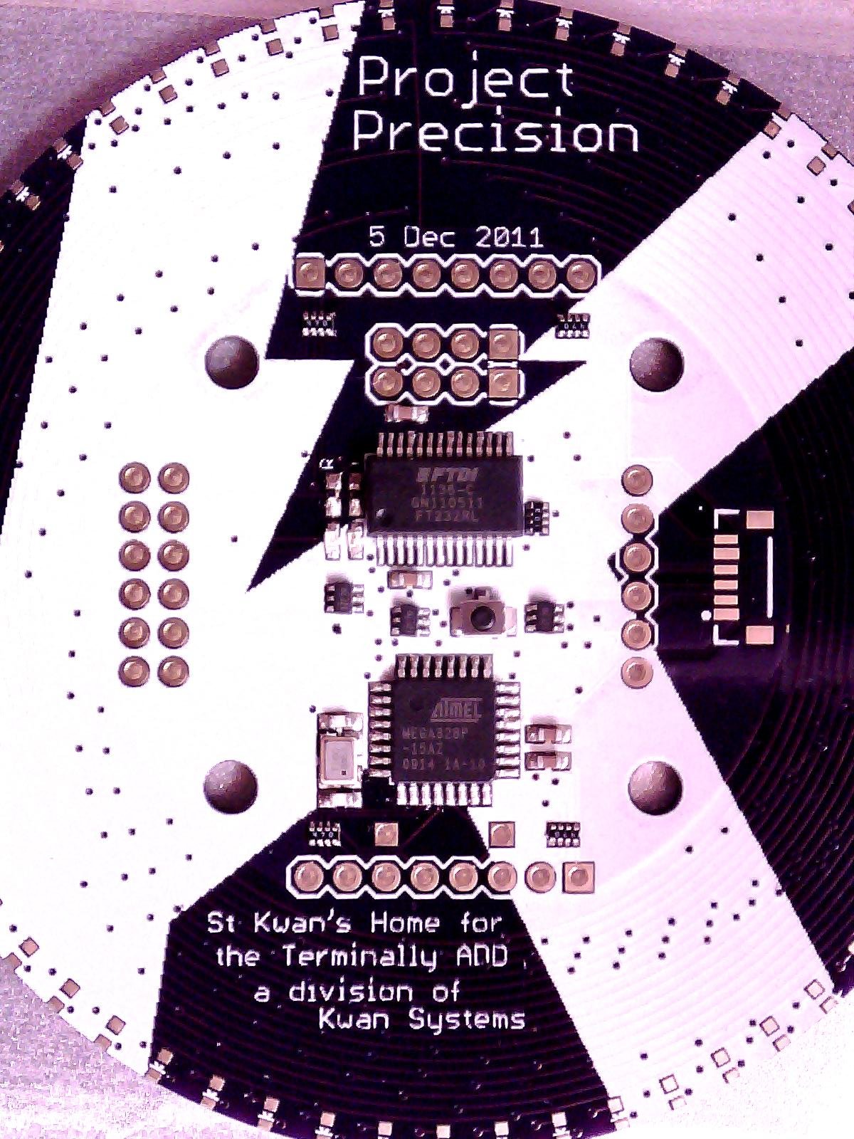
Way back in the late 80s, I remember seeing a TV show (I think it was Amazing Stories) which featured an interesting clock. It was round, black, about the same size as a normal wall clock, and all done up in LEDs. The LEDs appeared to be what I now recognize as pretty normal 5mm LEDs, in a ring around the edge of the clock, facing forward. It didn’t have any numbers, but from the motion of the lights, I could tell that it had an hour hand, a minute hand, a second hand, and one hand that went all the way around in one second.

Many years later, when I got into modern hobby embedded electronics, I remembered that clock and wanted to have it. Thus was born Project Precision. I also learned about the unit of time called the "third". See, once upon a time, sundials and mechanical clocks were so inaccurate that they just showed hours. Later, as technology marched on, they divided the hour up into tiny minute parts, called minutes. When clocks got even better, they did this a second time and got the second minute, or as we now call it, the second. Yes, this is really why the primary unit of time has a secondary name. Smaller divisions were also done, each one being 1/60 of the previous. So, we have third minutes (1/60 second, about 17ms), fourth minutes (1/3600 of a second, about 278 microseconds), fifth minutes (about 4 microseconds) and so on. My clock displays hours, minutes, seconds, and thirds. Smaller than that is measurable with a computer but not visible to the naked eye.

The clock has a red ring of LEDs closest to the center which represents hours, a yellow ring representing minutes, a green ring representing seconds, and a blue ring representing thirds. I originally was concerned that the third hand going around that quickly would be annoying, but some computer animations suggested that it would be OK. Just in case, I always had in mind the ability to disable the third hand, and that ability remains -- a small change in the code would disable the third hand.

I went through a couple of iterations. The first design only used 7400 series logic, and kept time by watching the zero crossings on the 60Hz AC mains frequency. A

third in this case would simply then be one cycle of AC. This design worried me, as I was taught proper respect for high-voltage in electronics class, and anything higher than about 12V is high for me.

The clock needed to be super-accurate in order to justify displaying the third hand. I originally considered adding a WWVB receiver, but by the time I actually got to implementing the project, GPS had progressed to the point where that was the solution that made sense.

The second design used an ARM microcontroller, a GPS module, and a smaller number of 7400 chips to manage 4 banks of 60 lights each. Neither of these designs got out of my circuit program.

Then one day I found out about Charlieplexing. This is a way to activate an enormous number of lights using a relatively small number of control signals - on the order of O(n^2). Charlieplexing has been well-covered in other places, so I will only discuss here the practical consequences I have fallen across in my experiences.

A clock with 4 hands, each with 60 lights, requires a total of 240 lights. The exact number of lights which can be controlled by a Charlieplex with n lines is n^2-n. With n=16, we have the ability to control… exactly 240 lights. The number of available pins on an ATmega328 is… exactly 16 pins. The ATmega328 seems to have been perfectly designed for this project.

Is it practical?

The first thing to do was to check if I could really do this. I wanted a wall clock with all of its hands done with LEDs, preferably each in its own color.The parts necessary are:

  • A round circuit board
  • A whole mess of LEDs
  • A GPS receiver module
  • A microcontroller with enough pins and current drive to handle the job

It rapidly became apparent that I didn’t want to do a full 9 inch circuit board. I get boards through Laen (now oshpark.com) for $5.00 per square inch of bounding box....

Read more »

  • 1 × ATmega328-P QFP32 Main microcontroller, hosting the application code and the Arduino bootloader
  • 1 × FT232 Interface and IO ICs / UART
  • 1 × UP501 GPS receiver GPS receiver. This one has a PPS output, runs at 3.3V, and is directly pin-compatible with the clock as built. Any other GPS with a PPS output can probably be made to work, which is a good thing since this part was discontinued.
  • 61 × Red LED in an 0603 surface-mount package I used Kingbright APG1608SURKC/T, which has a Vf of about 2.0V at a current of 20mA. One light is for the Rx light and the other 60 are for the hour hand.
  • 61 × Blue LED in an 0603 surface-mount package I used Kingbright APT1608QBC/D, which has a Vf of about 3.3V at an If of 20mA. One is for the Tx light and the other 60 are for the third hand

View all 12 components

  • February 28, 2012 - Drat!!!

    kwan321703/20/2017 at 22:58 0 comments

    Drat!!!

    Lights 4 and 5 on the back of the second board (where I am installing the blue lights) won't light. As it happens, neither will any of 54-59, but we'll save that part of the story for later.

    I remember the solder bridge between two pins, and one of those pins, A7, is involved with the lights that don't work. So, we carefully measure pin A7 and conclude that no matter how we program it, it acts like a high impedance. The natural conclusion is that it is burned out.

    So, run to Sparkfun, buy their last three ATmega328s, and a hot air rework station to pull the old chip. Carefully remove the old chip, taking care not to scorch the white paint on the board or blow away any of the passive components. When the chip comes off, it comes off great. Put in a new chip, verrrry carefully check continuity between each pin to make sure there are no bridges or missed joints. Fix a couple of missed joints. Guess what. The board acts exactly as it did.

    So, that theory is shot. I might have burned out pins on this chip, but exactly the same pins? I think not. Now time to gather more evidence for another theory. Write up a program that listens for commands on the serial port and turns individual signals high or low, with the rest at high-Z. Signals 1 and 16 are both no good. What is going on?

    The Arduino documentation says that you can use the analog input pins A0... as normal digital pins with the syntax pinMode(A0,OUTPUT); digitalWrite(A0,HI); etc. Which is in fact true, but only to a point. On an ATmega328, pins A6 and A7 are internally called ADC6 and ADC7, not PB...(ADC6) or anything like that. They are dedicated input pins. I had been planning (as in had a circut board made) to use A6 and A7 as Charlieplex lines 1 and 16. Guess which Charlieplex lines don't work... And guess which signals lights 4 and 5 (and 54-59) use...
    I have no one to blame for this but myself. It was right on the Eagle schematic symbol the whole time that all the other A0... pins were secondary uses of GPIO pins, but A6 and A7 were only labeled as ADC. I guess the weird part is that the crystal inputs and reset line are alternate uses of GPIO lines, but A6 and A7 are not.

    So, here's the plan. Lots of green wires, hot air, and razor blades, to hack D11 and D12 into P1 and P16. This will require giving up two multiplexers, which completely hashes my plan to use the GPS. At least this will let me test the charlieplex. Then, order 16 more blue lights, another FT232 and a correctly wired board which uses the crystal pins as two more digital outputs, allowing me to use D11 and D12 as multiplexer controllers on the next rev. NO getting a new board until all the green wires are fixed. Don't even touch Eagle until the last green wire is in place and CharlieTest works. Consider putting a LiPo battery power supply on the next board as well.

    The moral of the story is keep working the problem until you find the problem, and don't guess. I have a nice new hot air rework station which works really well, and costs more than the LEDs combined. Oh well.

  • February 23, 2012 - Desktop Microscopy and Charlieplexing

    kwan321703/20/2017 at 22:55 0 comments

    Desktop Microscopy and Charlieplexing

    One of the things I used to have to do with all my custom boards is takethem into the lab at work. There they have a really nice optical microscope. This one looks at things instead of through things, so it is appropriate for electronics (funny that, being in an electronics lab). It doesn't have an eyepiece as much as it has a facepiece. The end you look through has a screen (pure optical, no electronics or cameras involved) about 5 inches wide. It gives you a stereo view with a single objective lens, because each of your eyes is looking through a different optical path in the same set of lenses.

    I have been searching for something like that and finally restricted myself to something I could actually afford, a USB digital microscope. I ended up getting this microscope.

    Here's what I got it for - finding solder bridges
    Really short depth of field. Do you want the top of the chip in focus...
    ...or its leads?

    The subject of this particular set of pictures is Project Precision. For about five years now I have had a design in the back of my mind for a digital handed clock with an hour hand, minute hand, second hand and third hand (1 third = 1/60 second. Yes, really. Isaac Newton used thirds in the Principia.). I had a design using all 7400 series logic, a PIC and less 7400 logic, but finally came across the concept of charlieplexing. With 16 pins, I can control 240 LEDs. Only one at a time can be on, but I only need four on at a time, so I can strobe through those quickly enough.

    The thing is USB powered with no battery. It uses an ATmega328 as the core and an FT232 for USB-UART conversion. This basically makes it an Arduino. It has a port for a GPS receiver as well, and a couple of multiplexers to connect the ATmega, FT232, and GPS in any combination.

    What I'm most proud of is the layering. I needed 60 LEDs for each hand, and with four hands, I needed the front and back of two boards. I figured out a way to make these boards identical, so when I got three copies, I had enough, and didn't have to order three copies of two different boards.

    Charlieplexing involves pairs of LEDs, pointing in opposite directions. If you set one end of this combo to VCC and the other to ground, one of the pair will light. If you do it the other way, the other will light. What I have done is put half of each pair on one board, and the other half on the other board. All the LEDs on the board with the logic will point outward, while the LEDs on the other board will point inward. It's almost fate that 16 signals can control 240 LEDs, the exact number needed for four hands. 16 was the exact number of signals left on the ATmega after I accounted for the UART, clock, multiplexer controllers, etc.

    Now for the tedious task of picking and placing 240 diodes... Fortunately I only have to do them 60 at a time.

    No, I will not make one for you, not for any price. Well maybe, but it would have to be a lot. Better is to make one yourself.

  • February 24, 2012 - It's Alive!

    kwan321703/20/2017 at 22:46 0 comments

    It's alive!

    I finally invent something that works!
    -- Dr Emmett Brown

    Well, I have just built an honest to goodness Arduino, a round one connected to the most elaborate Charlieplex I have ever heard of... but no light on D13, so I can't even test it with the Hello World for microcontrollers, blinking a light. So, I used the ASCIITable example, to see if I can get code on the machine and have it run.

    I made (at least) one mistake in the board design, and had to run what may be the shortest green wire ever. The FT232 datasheet clearly states that the TEST pin must be grounded, or the device will go into test mode and not show up on USB as expected. Well, I didn't ground TEST on the circuit board, and the device didn't work as expected. However, there is one bit of good news. The pin right next to it is ground. So, one bridge removed from the ATmega, and one added to the FT232, and we are ready to go.

    First, load the ArduinoISP onto the Nano 3.0 I have.

    Next, connect it to Project Precision, while the Nano is unplugged.

    Neither of the Arduinos involved look like this

    I cleverly broke out the six pins needed to do this on Precision, so it just needs a ribbon cable from a breadboard to the connector on Precision. I used individual jumper wires to connect the pins on the Nano by label to the correct wire in the ribbon cable.

    Next, plug everything in. First carefully check that the ribbon is plugged in right, then plug the Nano into USB.

    Now run the bootloader instructions. All four lights on the Nano will light up simultaneously (something I hadn't seen before) and blink like crazy (except the blue power light).

    Board the device and bring it to life!

    Finally, pull the plug on the Nano and plug in Precision. I thought about writing a literal "Hello World" program, but it was just easier to run the ASCIITable sketch.

    ASCII Table ~ Character Map
    !, dec: 33, hex: 21, oct: 41, bin: 100001
    ", dec: 34, hex: 22, oct: 42, bin: 100010
    #, dec: 35, hex: 23, oct: 43, bin: 100011
    $, dec: 36, hex: 24, oct: 44, bin: 100100
    %, dec: 37, hex: 25, oct: 45, bin: 100101
    &, dec: 38, hex: 26, oct: 46, bin: 100110
    ', dec: 39, hex: 27, oct: 47, bin: 100111
    (, dec: 40, hex: 28, oct: 50, bin: 101000
    ), dec: 41, hex: 29, oct: 51, bin: 101001
    *, dec: 42, hex: 2A, oct: 52, bin: 101010


    and so on for all 94 printable characters.

    I wasn't happy with the stencil and solder paste on the edge of the board, So, on to soldering 240 surface mount LEDs by hand!

View all 3 project logs

Enjoy this project?

Share

Discussions

Similar Projects

Does this project spark your interest?

Become a member to follow this project and never miss any updates