 kwan3217
I finally invent something that works!
-- Dr Emmett Brown
Well, I have just built an honest to goodness Arduino, a round one connected to the most elaborate Charlieplex I have ever heard of... but no light on D13, so I can't even test it with the Hello World for microcontrollers, blinking a light. So, I used the ASCIITable example, to see if I can get code on the machine and have it run.
I made (at least) one mistake in the board design, and had to run what may be the shortest green wire ever. The FT232 datasheet clearly states that the TEST pin must be grounded, or the device will go into test mode and not show up on USB as expected. Well, I didn't ground TEST on the circuit board, and the device didn't work as expected. However, there is one bit of good news. The pin right next to it is ground. So, one bridge removed from the ATmega, and one added to the FT232, and we are ready to go.
First, load the ArduinoISP onto the Nano 3.0 I have.
Next, connect it to Project Precision, while the Nano is unplugged.
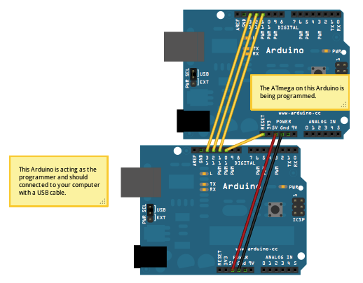 |
| Neither of the Arduinos involved look like this |
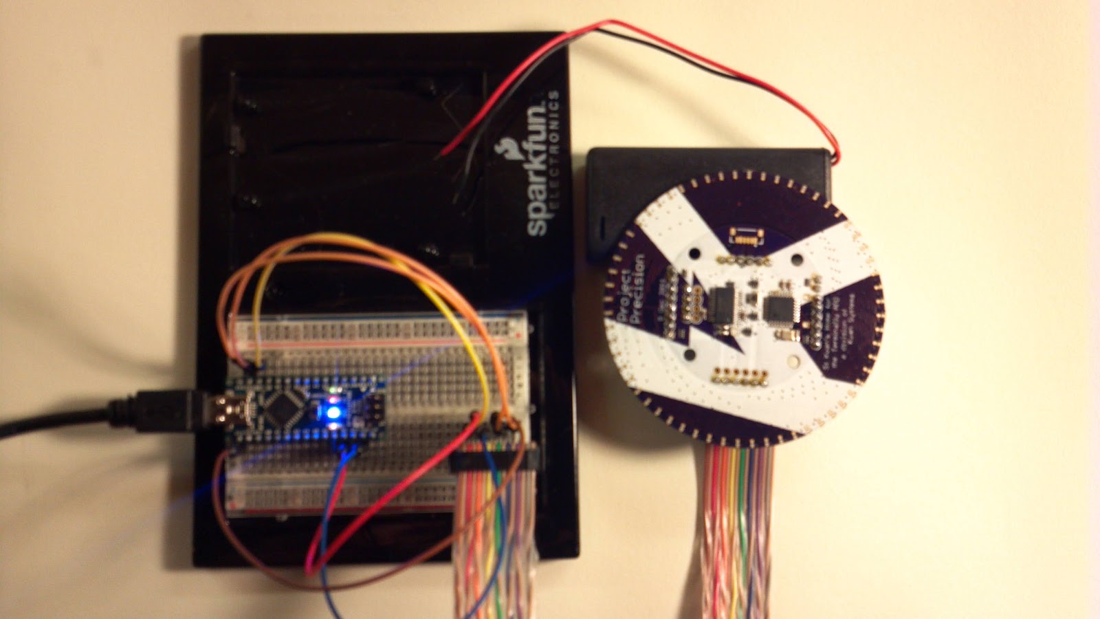
I cleverly broke out the six pins needed to do this on Precision, so it just needs a ribbon cable from a breadboard to the connector on Precision. I used individual jumper wires to connect the pins on the Nano by label to the correct wire in the ribbon cable.
Next, plug everything in. First carefully check that the ribbon is plugged in right, then plug the Nano into USB.
Now run the bootloader instructions. All four lights on the Nano will light up simultaneously (something I hadn't seen before) and blink like crazy (except the blue power light).
 |
| Board the device and bring it to life! |
Finally, pull the plug on the Nano and plug in Precision. I thought about writing a literal "Hello World" program, but it was just easier to run the ASCIITable sketch.
ASCII Table ~ Character Map
!, dec: 33, hex: 21, oct: 41, bin: 100001
", dec: 34, hex: 22, oct: 42, bin: 100010
#, dec: 35, hex: 23, oct: 43, bin: 100011
$, dec: 36, hex: 24, oct: 44, bin: 100100
%, dec: 37, hex: 25, oct: 45, bin: 100101
&, dec: 38, hex: 26, oct: 46, bin: 100110
', dec: 39, hex: 27, oct: 47, bin: 100111
(, dec: 40, hex: 28, oct: 50, bin: 101000
), dec: 41, hex: 29, oct: 51, bin: 101001
*, dec: 42, hex: 2A, oct: 52, bin: 101010
and so on for all 94 printable characters.
I wasn't happy with the stencil and solder paste on the edge of the board, So, on to soldering 240 surface mount LEDs by hand!
Discussions
Become a Hackaday.io Member
Create an account to leave a comment. Already have an account? Log In.