 Rory
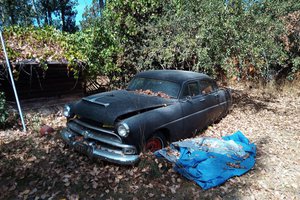
RoryThe aim of the project is to fit a turbo charger to the engine and reliably make the car faster. There are a few main areas of work to consider
Engine management (ECU)
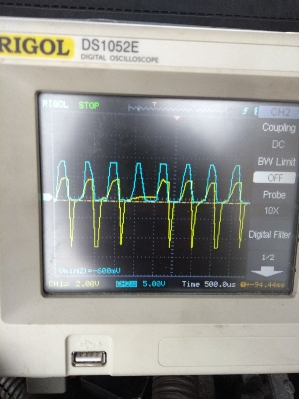
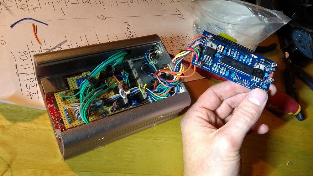
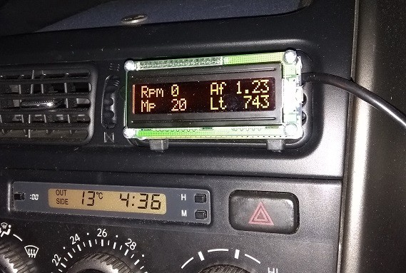
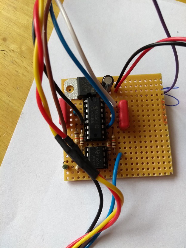
I will be using a microcontroller (Arduino or similar) to supply more fuel to the engine when required. Extra fuel will be calculated by comparing the engine RPM and boost pressure to values in a look up table (the fuel map).
The factory ECU will be responsible for normal running of the engine. I will be adding fuel and adjusting timing where needed. I have a couple of ideas on how to do this which will be discussed in the build logs.
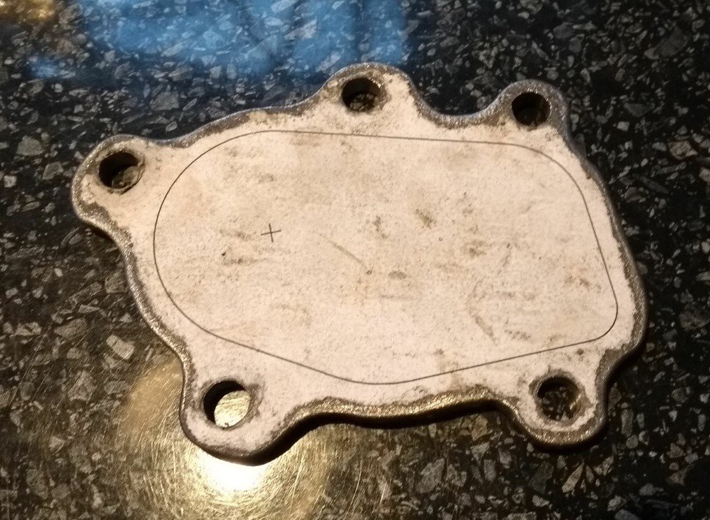
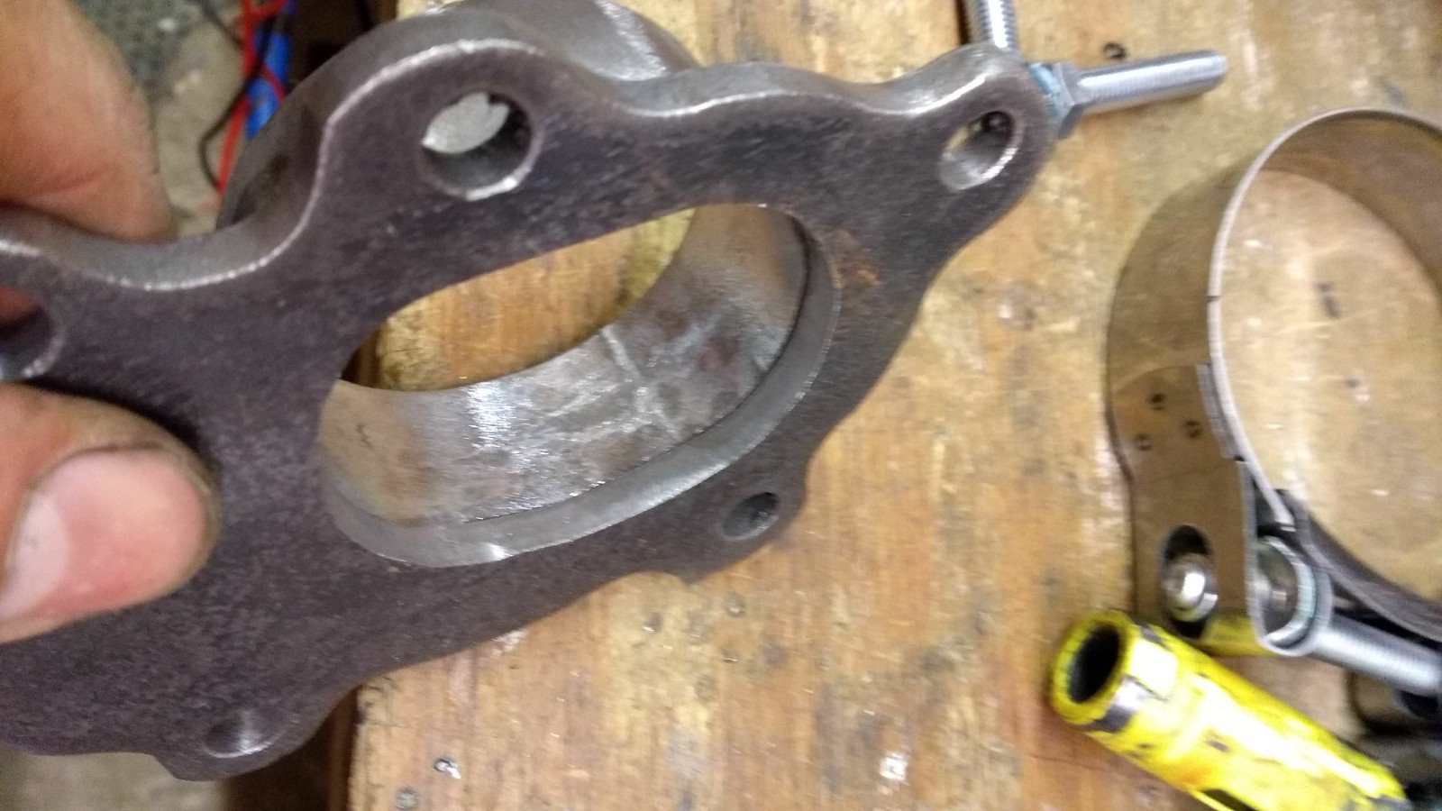
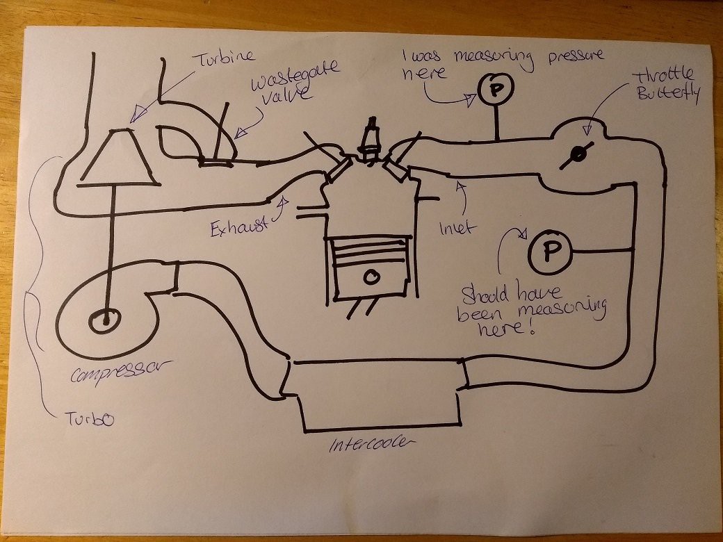
Exhaust Modifications
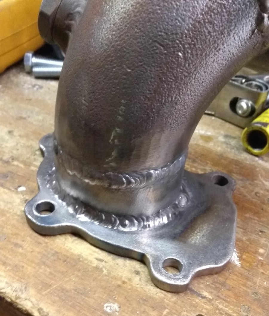
The exhaust and Inlet manifolds need to be plumbed into the turbo. I will make a new exhaust manifold to the turbo using laser cut flanges. The manifold will be steel to save costs and ease of fabrication. Stainless manifolds require back purging of the inside of the manifold to stop corrosion. This uses allot of argon which is costly. The output of the turbo will connect to the existing exhaust. I intend the turbo exhaust side to be a straight swap with the existing exhaust headers.
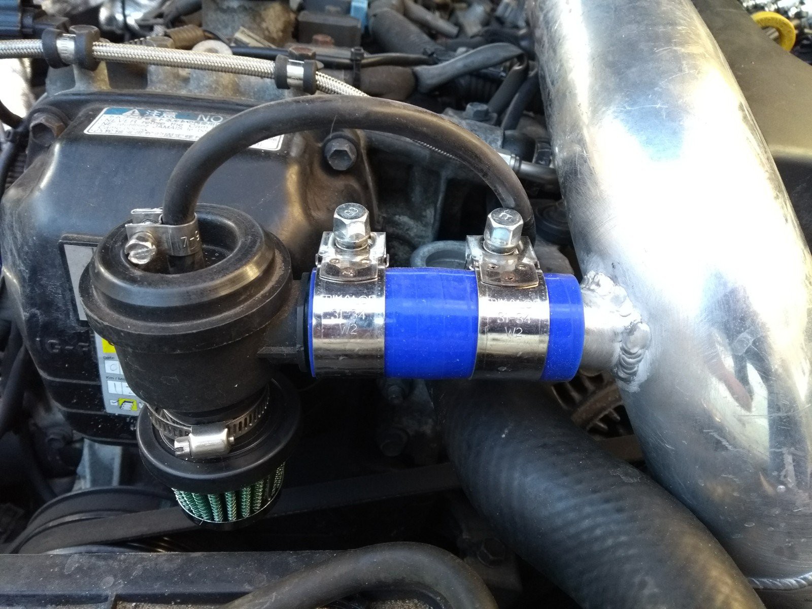
Inlet Modifications
The cold side of the turbo will pass through an intercooler mounted inside of the front bumper. There is already a grill of good dimensions available. I don’t want to have to cut any part of the front of the car to keep it looking stock. Plumbing will be aluminium pipework made to accurately fit the engine bay with a minimum of silicone joiners.
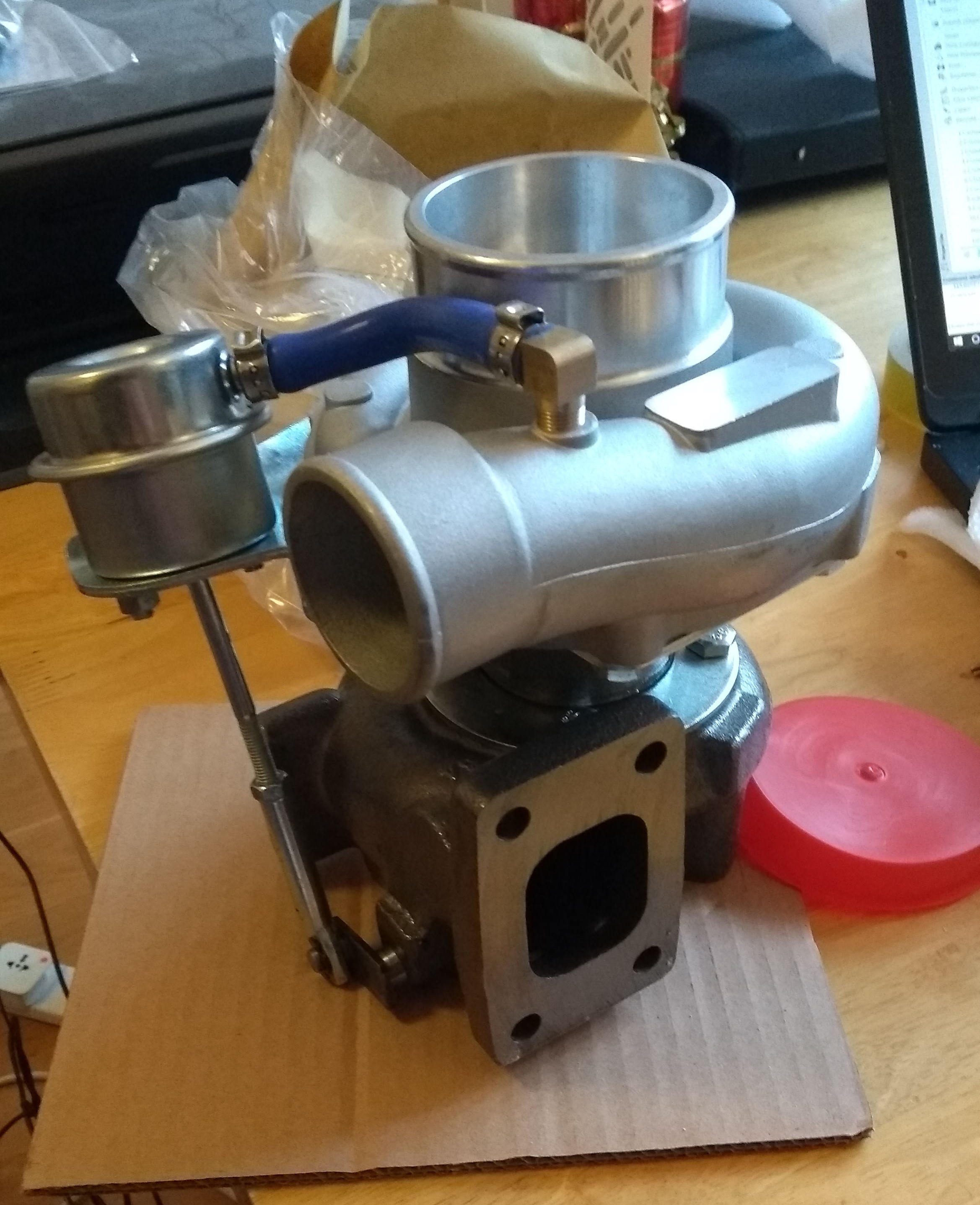
Turbo Sizing
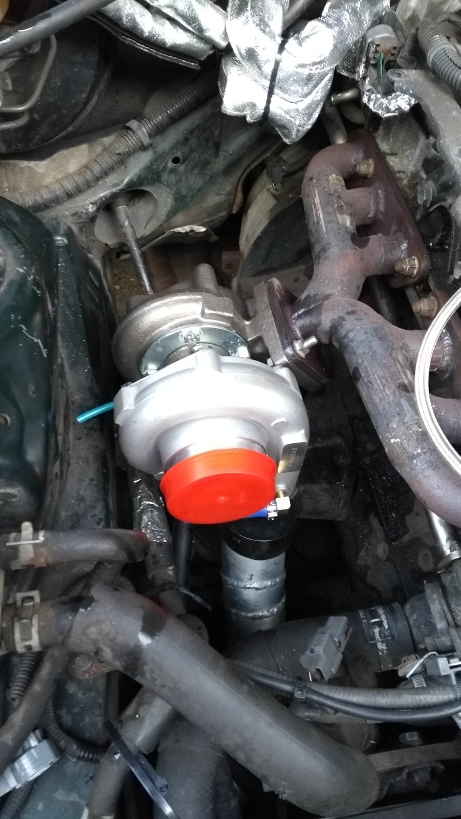
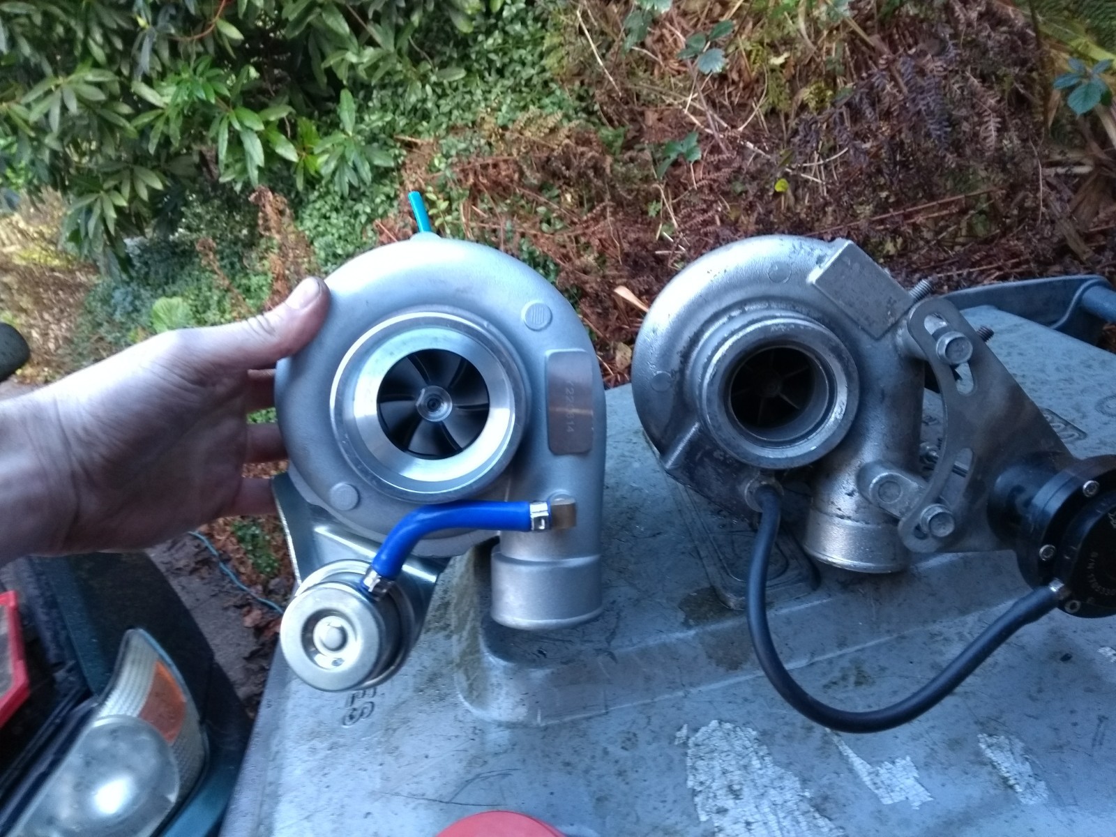
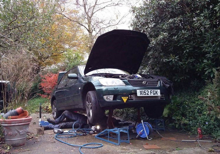
I am not going for an enormous increase in power by turbo project standards (+80HP) and I want the car to be driveable. I need to accurately size the turbo to the car to avoid turbo lag. On a whim i brought a second hand turbo from a Saab 9-5, part number TD04-15T, originally from a 2.3L 230HP engine. We will see how this goes...
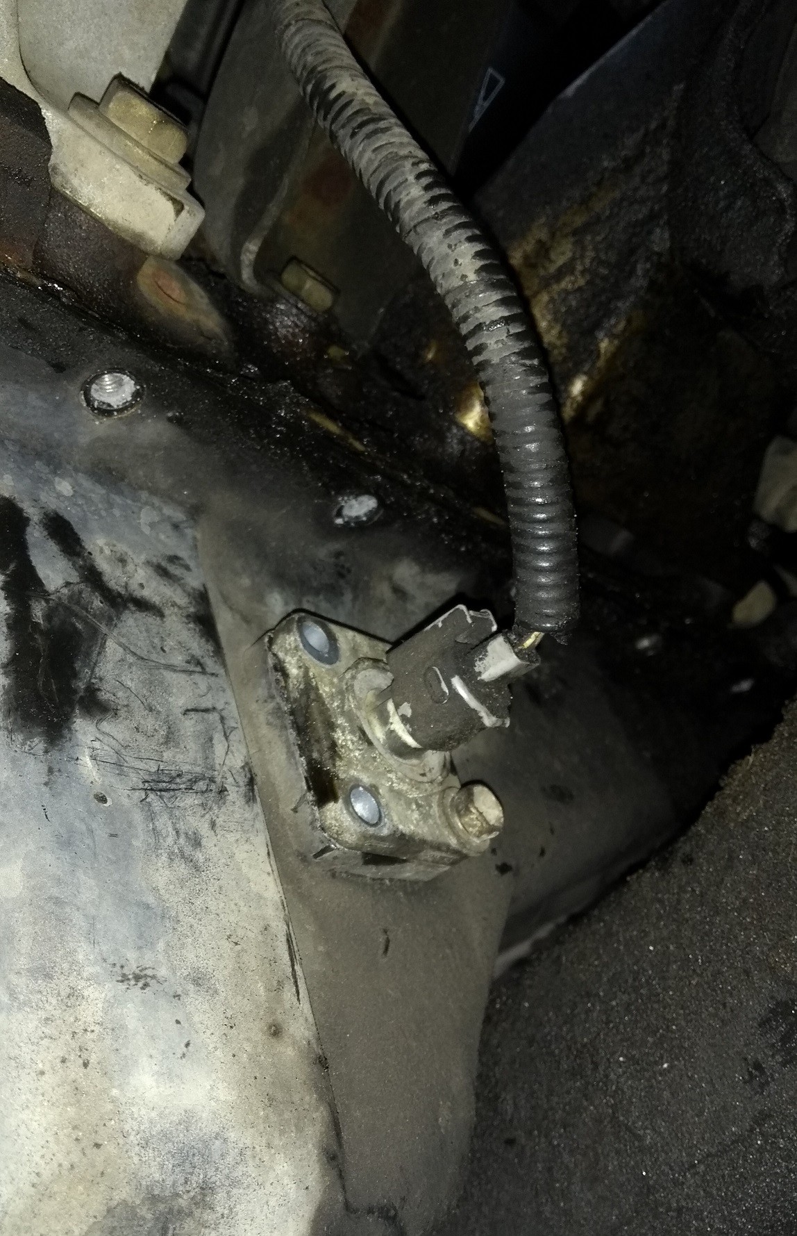
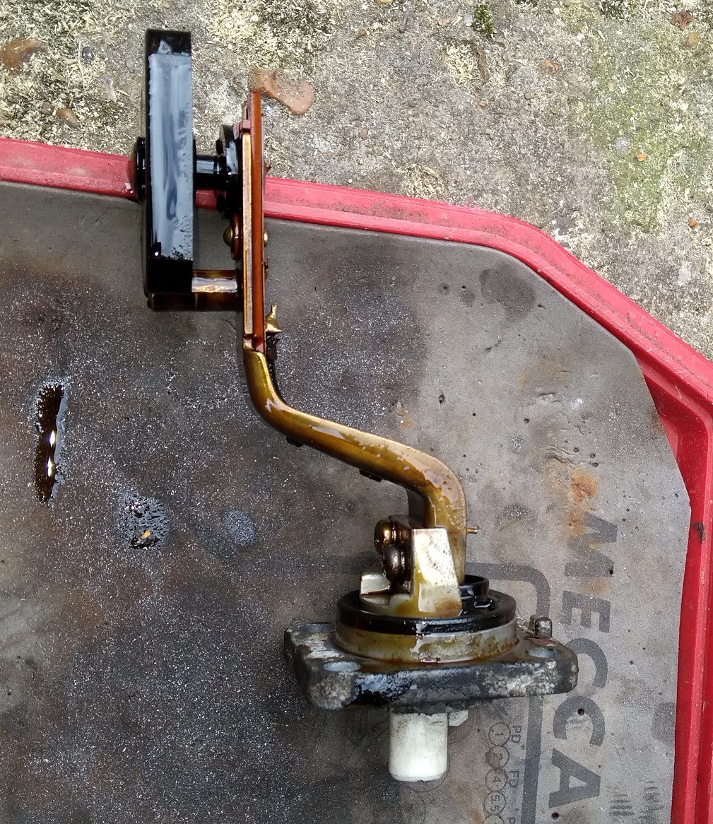
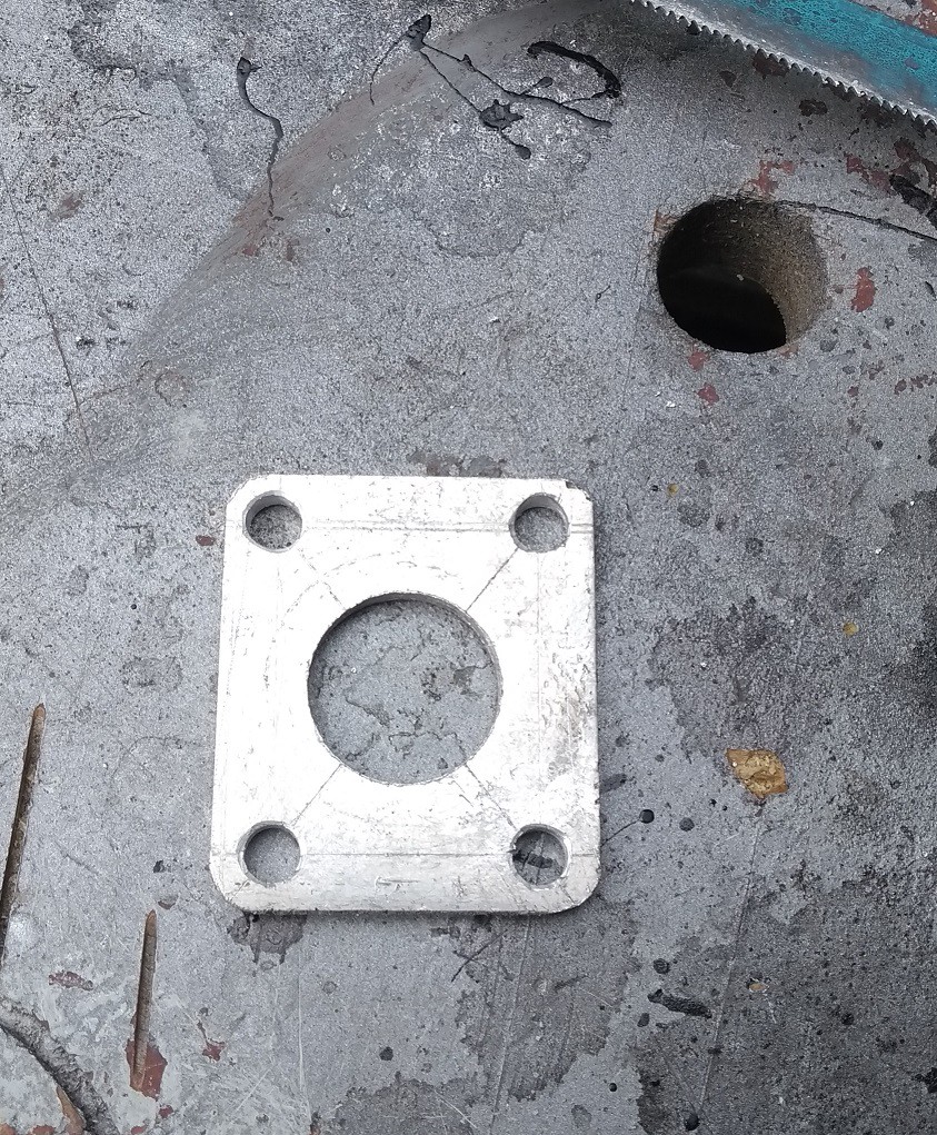
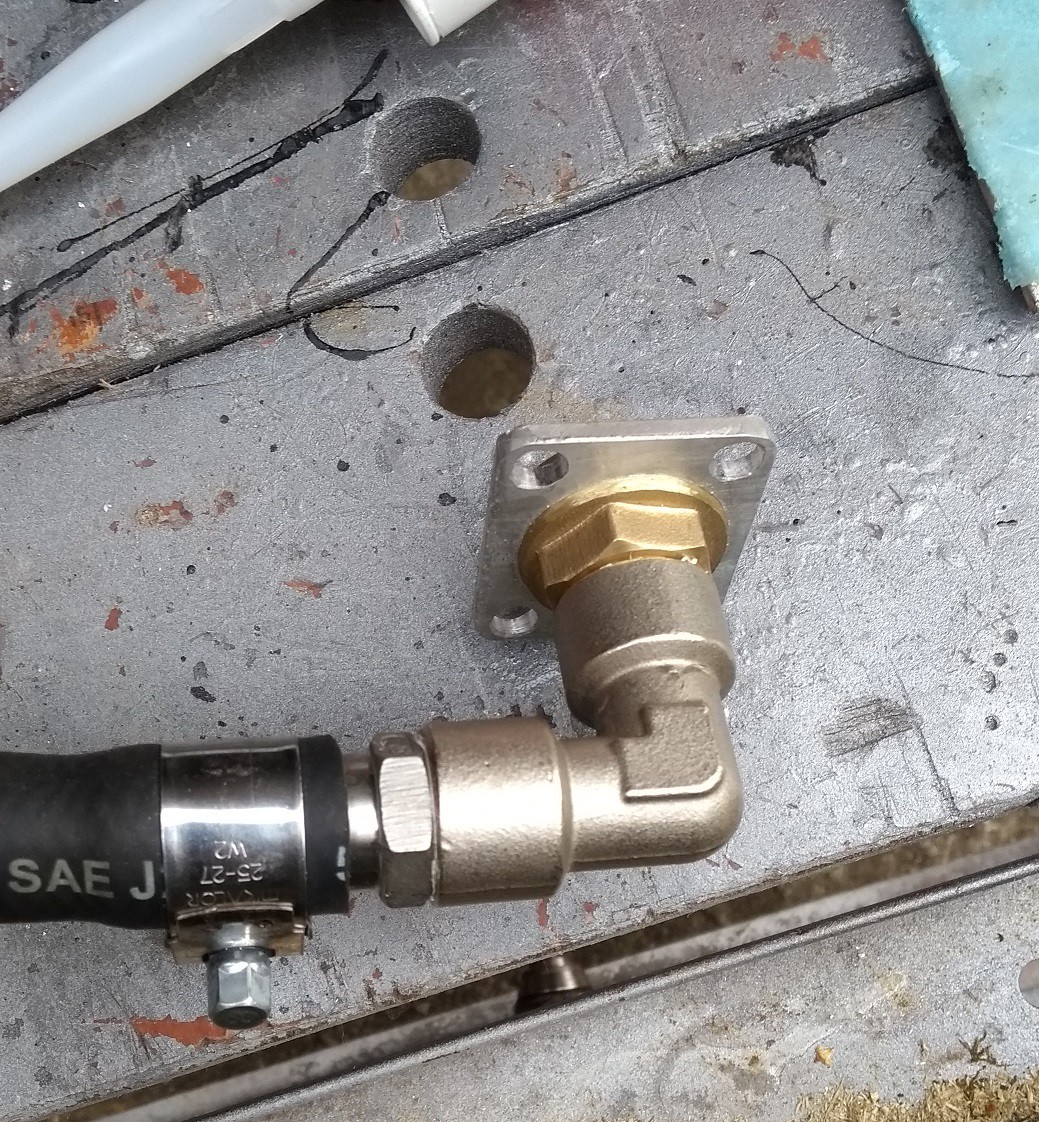
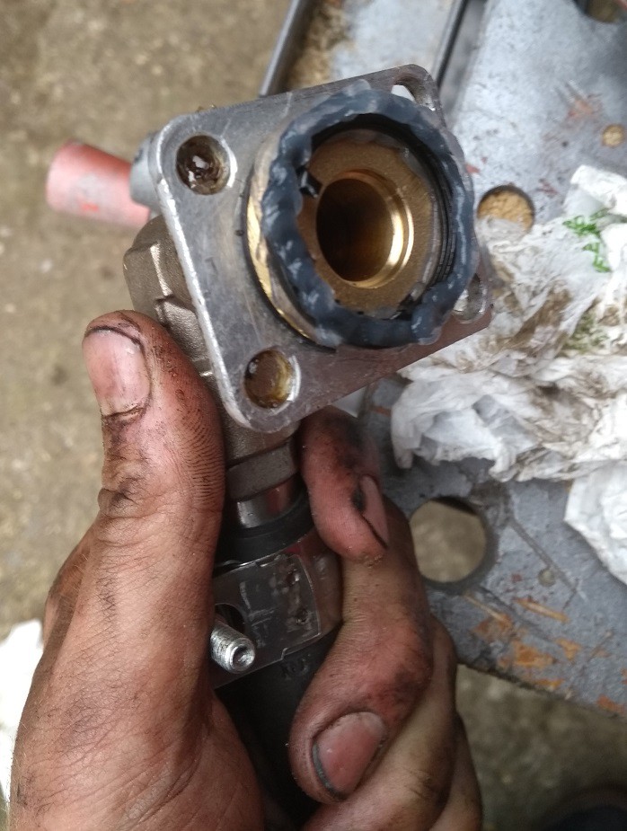
Turbo oil feed/drain
The oil drain is now fed through a port in the sump originally used by the oil level switch.

 Sky Shorba
 Meow
Meow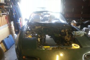
 Michael Nuro Spetås
If you have time I have a few questions about your piggy back design.