 Rory
RoryLong time since may last update. Been busy with other things but I have been able to push the project forward in the last few weeks.
I have finished the exhaust manifold. Here it is fitted to the car. Luckily it didn’t move much whilst welding and the flanges fit well. I may need to get them skimmed to seal properly but I won’t really know until I run the car for the first time
I have finished the exhaust manifold. Here it is fitted to the car. Luckily it didn’t move much whilst welding and the flanges fit well. I may need to get them skimmed to seal properly but I won’t really know until I run the car for the first time.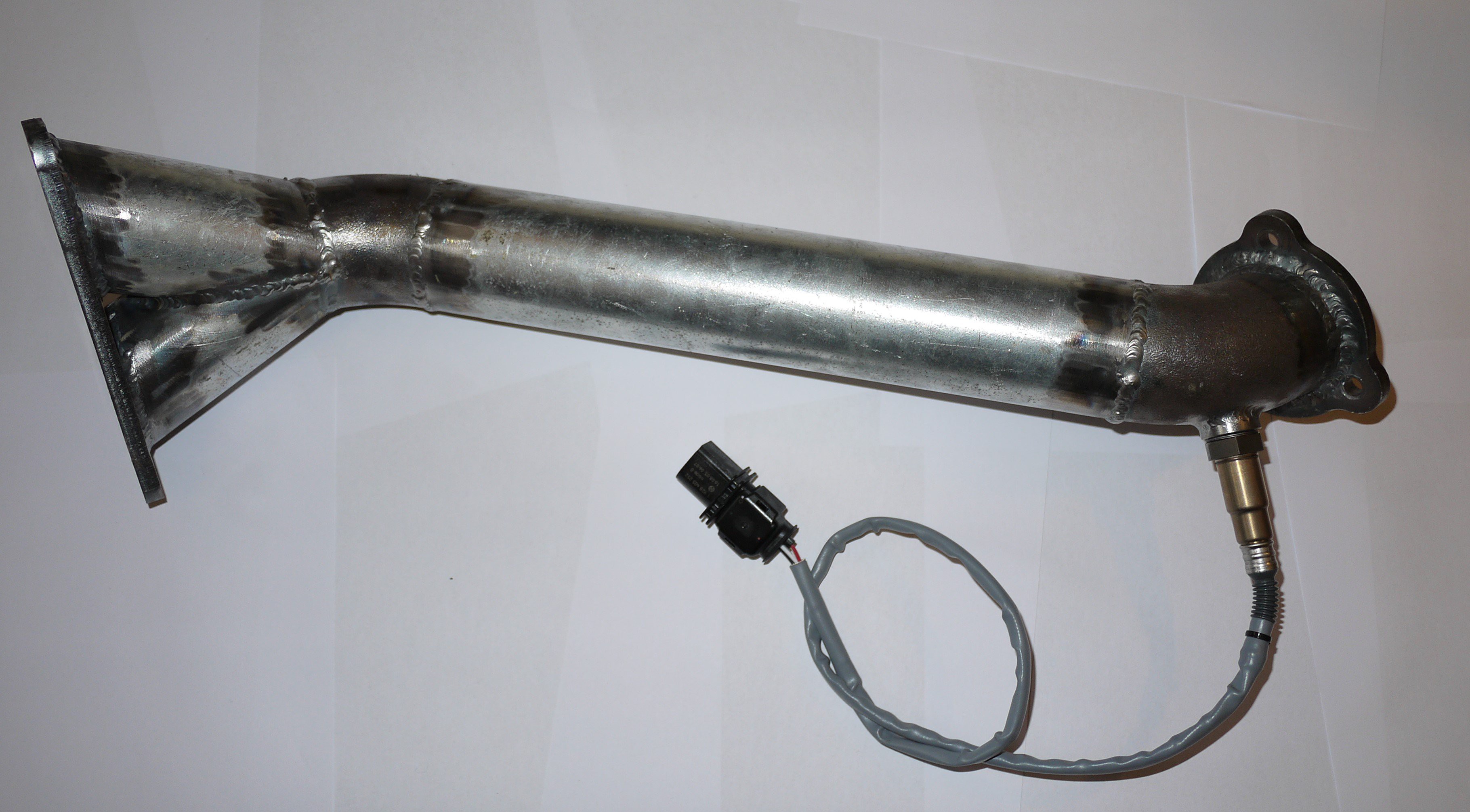 | 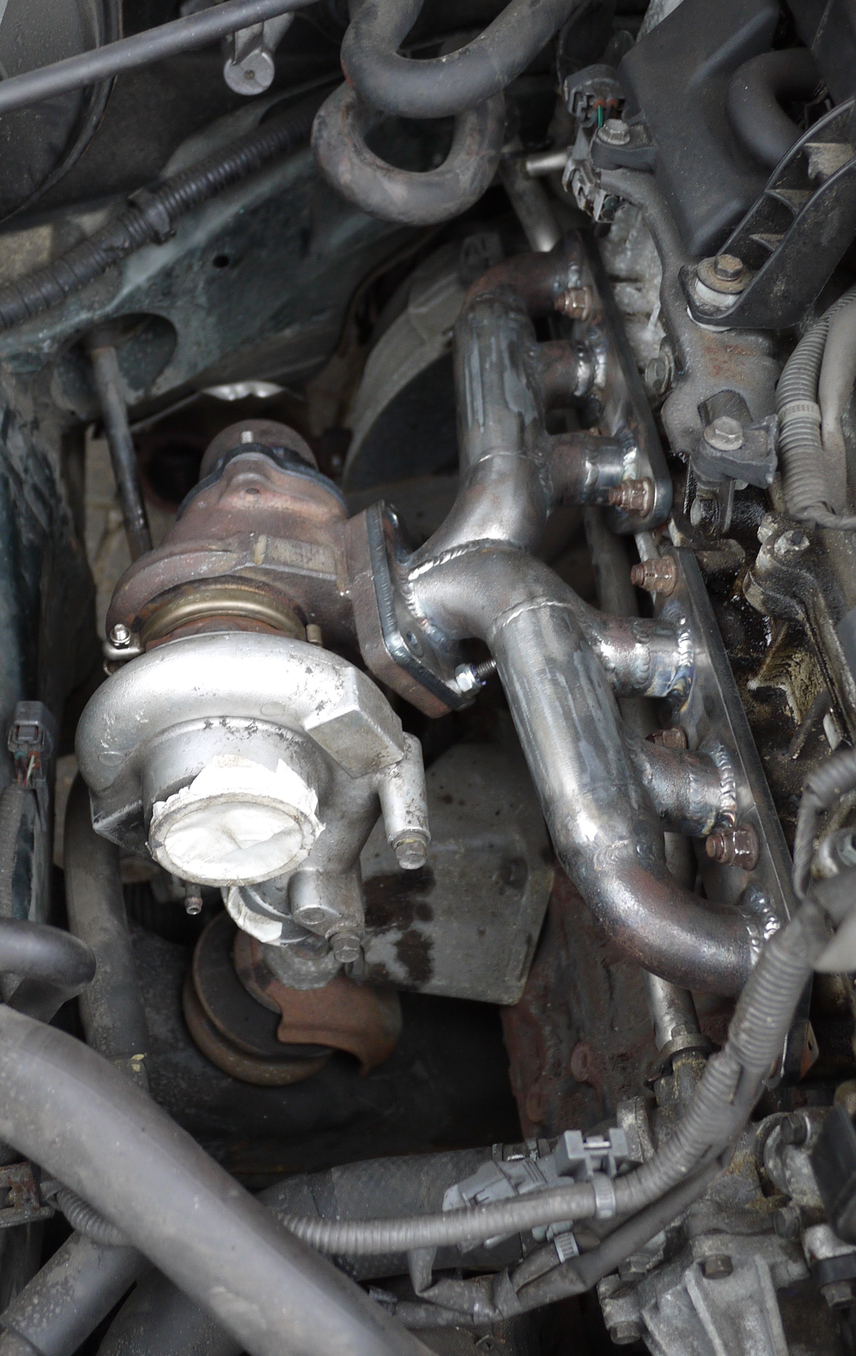 |
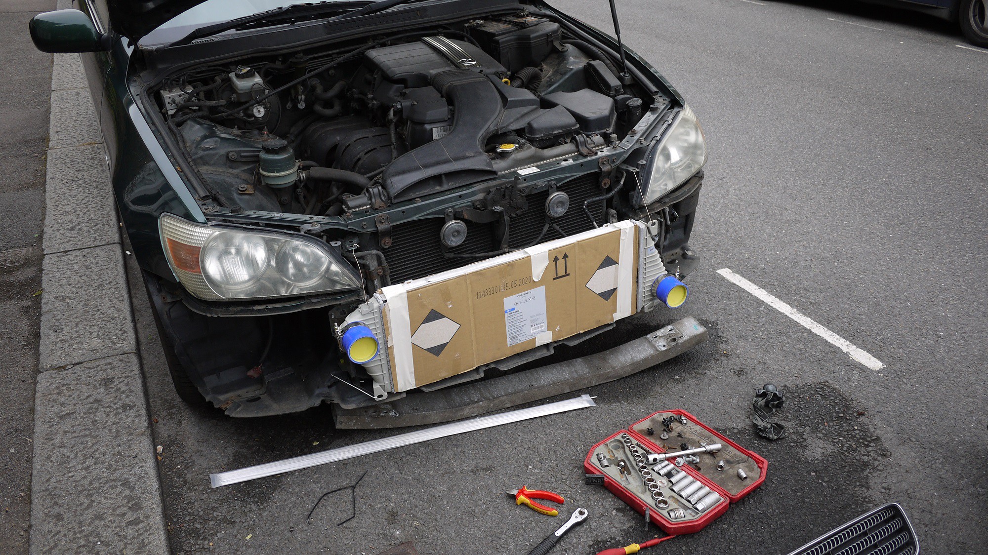
I spent some time messing about with the cold side of the system. I originally brought a Mercedes sprinter intercooler. These are very cheap and have 63mm tube connections. I couldn’t really find any dimensions at the time so just ordered one brand new for £38 delivered. As you can see it was far too big. It could have been squeezed In I suppose but I would have had to cut up the front bumper allot, run the car without the front crash protection bar and the plumbing would have been messy as the tubing would have had to come forward before heading back into the engine bay, as the photo.
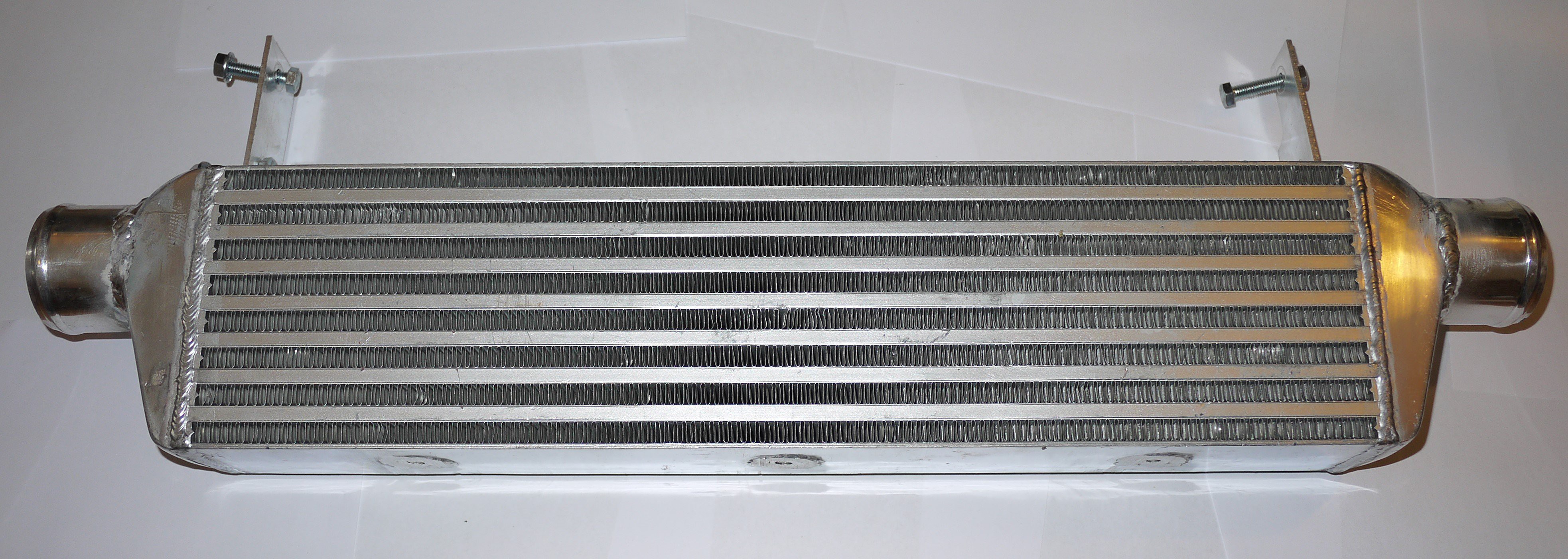
After this I had a good measure up and found a bargain on ebay. I now have an intercooler with dimensions 550x140x65. This fits very nicely. It was cheap because it came pre-damaged. It still holds air though. I added some brackets and it now mounts to the crash protection bar that fits inside the front bumper. I also welded on some 63mm tube connections to match my pipework. This was the first time I have welded anything important in aluminium (after about 2 hours practice) it’s not impossible but my efforts here are very messy. I wont give you any close up photos! It is still air tight though.
I ordered an ebay special intercooler tubing kit. I was quite impressed with this. You get everything you see in this picture for £80 delivered. I had to buy a couple of silicone elbows purely because the radius of the bends in the kit are quite large, about 100mm.
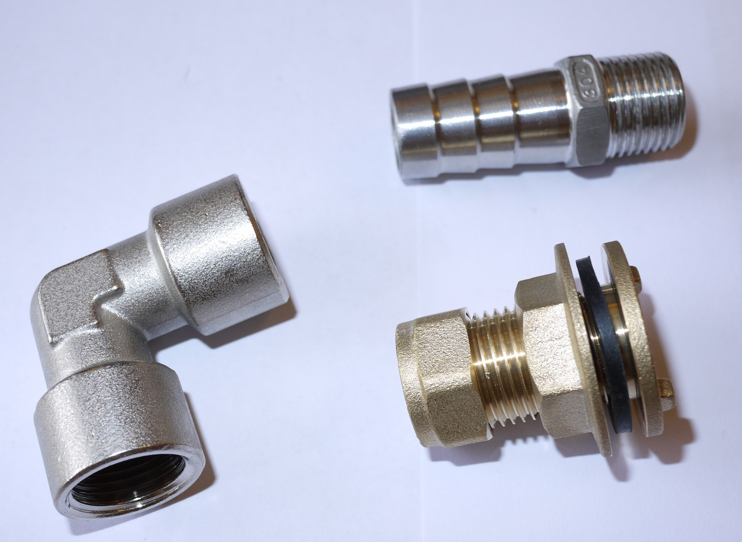
I have ordered a custom braded line for the turbo oil feed. I have the bits for the turbo water flow and return as well. For this I am using standard M12x1.5 banjo to hose barb fittings. The flow and return will tee into the throttle body heater lines.
| I ordered an ebay special intercooler tubing kit. I was quite impressed with this. You get everything you see in this picture for £80 delivered. I had to buy a couple of silicone elbows purely because the radius of the bends in the kit are quite large, about 100mm. | 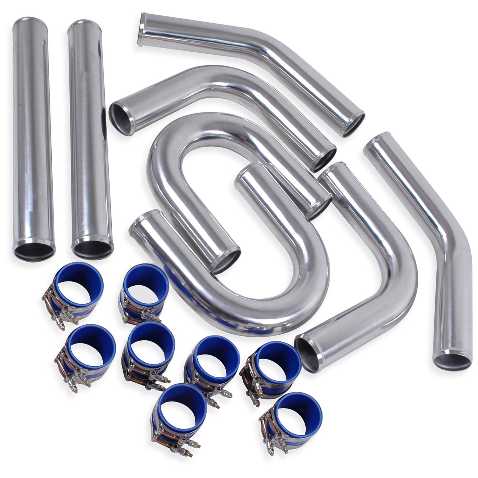 |
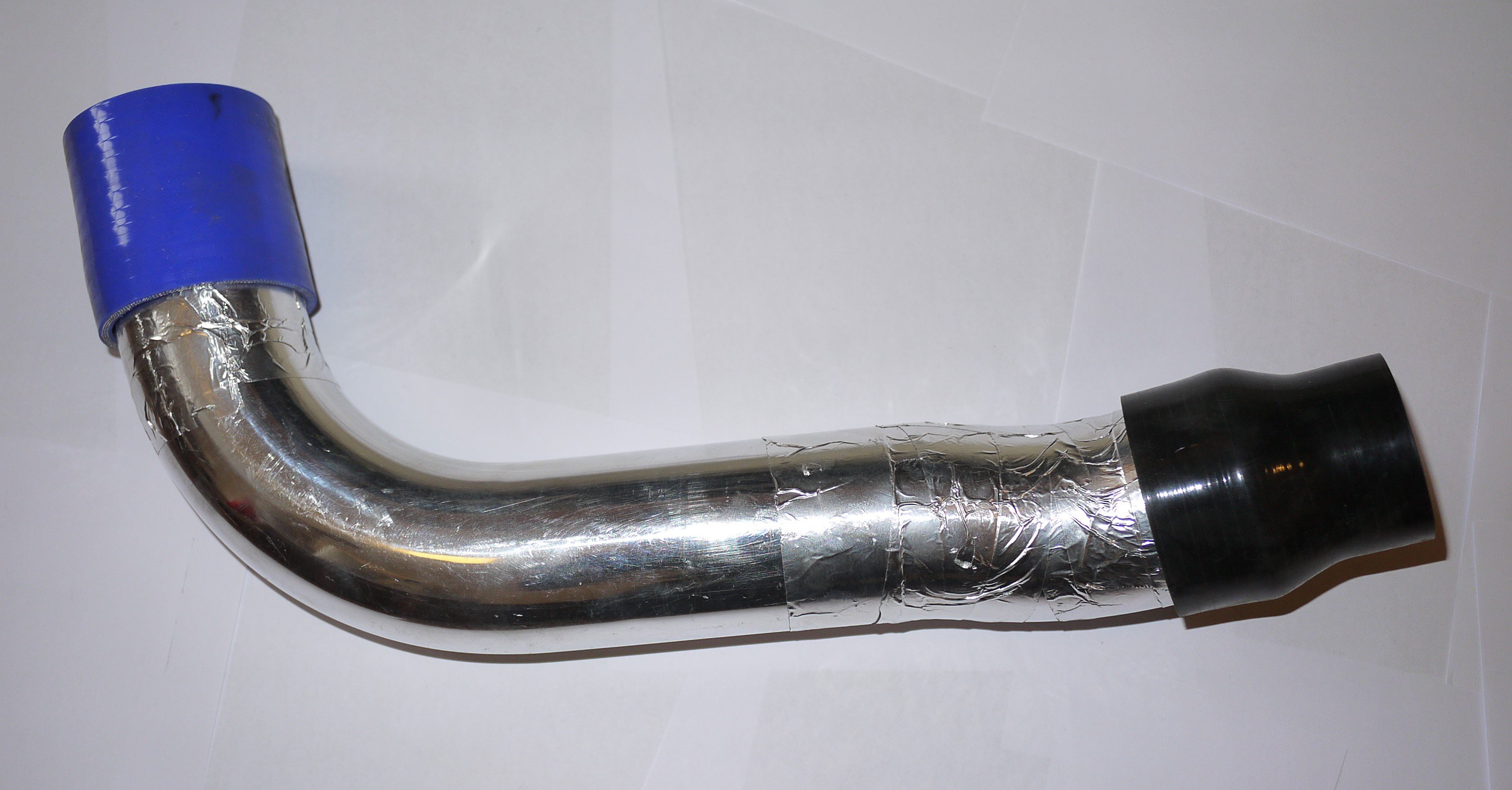 | I have mocked up all of the tubing with aluminium tape ready for welding. I had planned to do the welding in a couple of hours last weekend but that was a bit ambitious. I need much more practice before I attempt this. The tube has a 1.5mm wall and is very unforgiving for bad welding technique. I was using 2.4mm tungsten’s and filler. A bit of research suggests the use of 1.6mm filler and perhaps a 1.6mm tungsten. I think my shielding gas flow was much too high as well causing turbulence. Luckily I did not need the two straight sections in the kit so this give me plenty of material to practice with. |
I have ordered a custom braded line for the turbo oil feed. I have the bits for the turbo water flow and return as well. For this I am using standard M12x1.5 banjo to hose barb fittings. The flow and return will tee into the throttle body heater lines.
The turbo oil drain needs to feed straight back to the sump for which I need to attach a hose fitting. My sump is pressed steel so I can’t drill and tap a fitting into it. I could have welded something on but I didn’t want to risk warping it and cause oil leaks from the sealing surfaces. A bit if ebaying got me the following: A ‘15mm compression tank connector’ will seal into the sump. 15mm copper compression fittings have a ½’’ BSP male thread so I can use a female threaded elbow to join this to a 19mm hose barb. This was a mm or so too large but it’s all that I could find.
So the mechanical side is nearly finished. I need to spend some time on the electronics. My original plan was to use a micro controller to hold the fuel injectors open after they had been fired by the ECU for a period calculated by the boost pressure and the engine RPM. This is complicated and timing critical so I have been trying to come up with something more simple. I’m thinking along the lines of an electronically controlled fuel pressure regulator. It will have its own project page as I can’t find anyone that has done this.
Discussions
Become a Hackaday.io Member
Create an account to leave a comment. Already have an account? Log In.