Peter McCloud
-
Arduino Hardware Completed
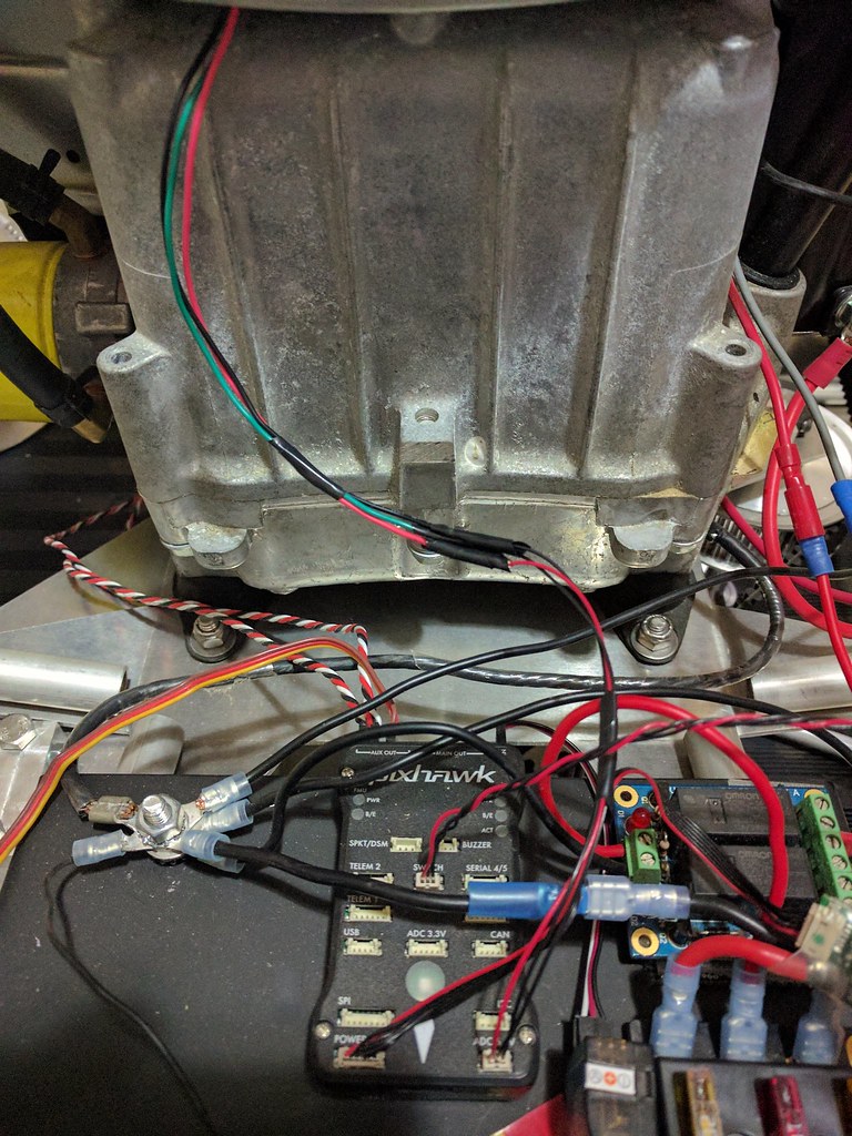
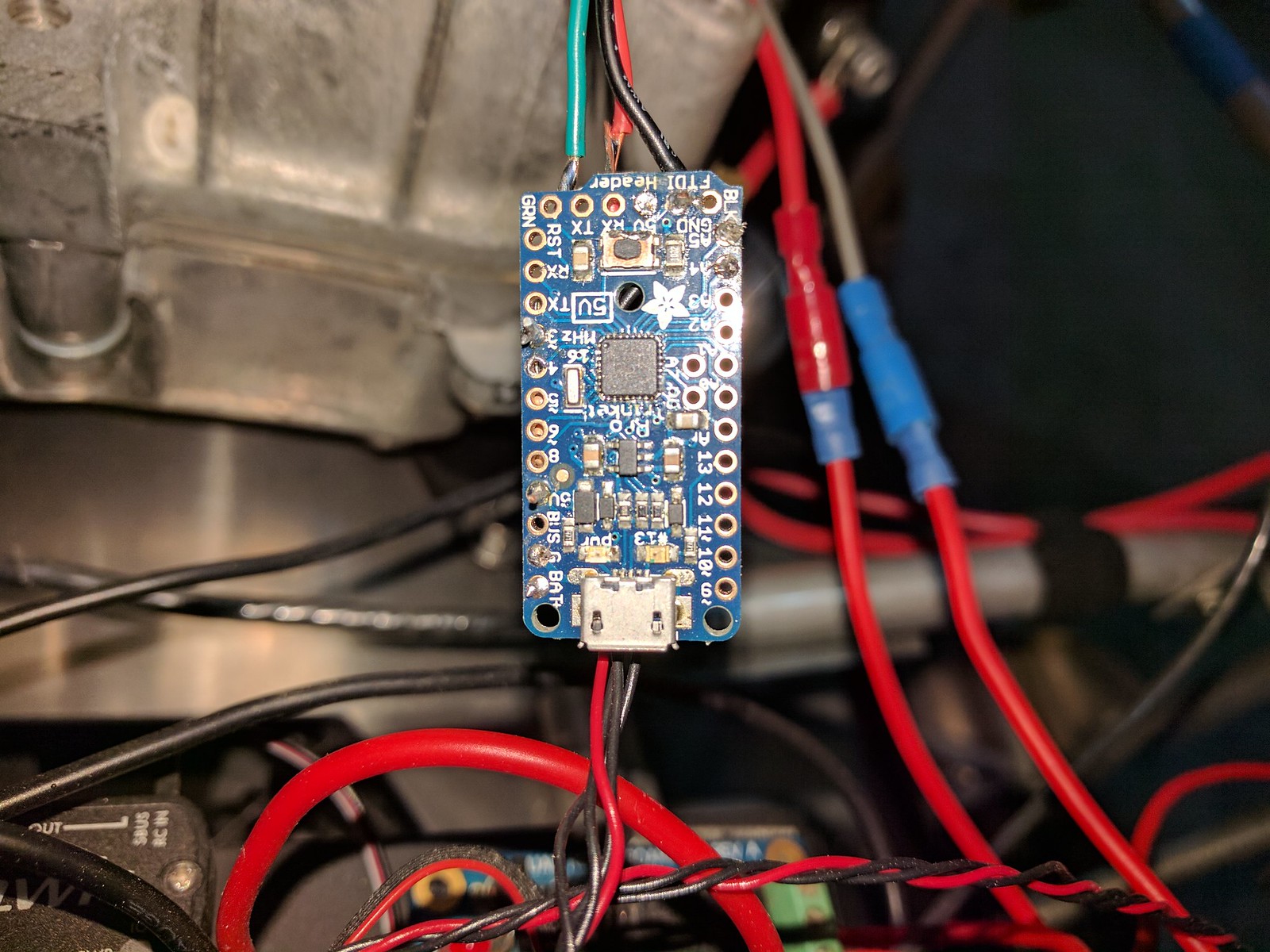
04/07/2017 at 22:05 • 0 commentsThe Trinket Pro (arduino) hardware has been soldered together and has been installed on the vehicle. Below is the Trinket Pro connected to the Pixhawk I2C and the hall effect sensor. The arduino is powered from the 5V power provided by the Pixhawk I2C port.
![]() The hall effect sensor is a uni-polar sensor meaning that the sensor only gets triggered by a specific orientation to a magnetic field. For this case the back of the sensor case has to be facing the flywheel magnet.
The hall effect sensor is a uni-polar sensor meaning that the sensor only gets triggered by a specific orientation to a magnetic field. For this case the back of the sensor case has to be facing the flywheel magnet.![]() The sensor was also re-positioned to be level with the middle of the magnet.
The sensor was also re-positioned to be level with the middle of the magnet.![]() A quick test of the setup was done to make sure the electronics work. The arduino was configured to blink the on-board LED when the magnet was detected. Then the engine was spun by hand to pass the magnet by the sensor. The arduino correctly detected the magnet and flashed the LED each time the magnet passed by.
A quick test of the setup was done to make sure the electronics work. The arduino was configured to blink the on-board LED when the magnet was detected. Then the engine was spun by hand to pass the magnet by the sensor. The arduino correctly detected the magnet and flashed the LED each time the magnet passed by.The next step is to add the logic to the arduino to compute the frequency and then pass that to the Pixhawk via I2C.
-
Switching from the ADC port to I2C
03/18/2017 at 16:29 • 0 commentsMy initial concept was to use a Hall Effect sensor connected to the ADC port on the Pixhawk. However it turns out that using the ADC port isn't an option. It turns out that the ADC ports don't support interrupts. The ports are good for reading sensors, but without interrupts, there's no way to count the pulses to get a frequency measurement.
There are ways to measure frequency with the Pixhawk directly. There are 8 main pins and 6 aux pins that are capable of measuring frequency. However the 8 main pins are being used for controls and the 2 of the aux pins are being used for servo to control the engine (throttle and choke). This would leave 4 open aux pins, but it turns out the for my particular hardware (px4fmu-v2), the aux pins can either be all PWM or all GPIO, but not a mix. Since the 2 servos are required, that means the rest are unusable as GPIOs.
This means that most likely I'll have to an off-board option. A separate device to determine the frequency and pass the data to the Pixhawk via on of the many other data ports. The simplest option for now appears to be using an Arduino to measure the frequency and use I2C to pass the frequency measuring to the Pixhawk. I've got some Trinket Pros on-hand, so I'll start prototyping with that.
-
Sensor connected
03/13/2017 at 03:07 • 0 commentsThis project started almost two years ago when the hall effect sensor was first installed underneath the engine cover. The sensor is in a TO-92 package and wire leads were soldered on. The wire was run through a hole underneath the flywheel. The sensor is held in place with a little bit of RTV. Below the installed sensor is shown along with the magnet that is present on the flywheel.
![]() Today the sensor was connected to the Pixhawk ADC port. The wire leads were spliced onto 3 pin Hirose connector and a 10k resistor was added between the power and signal lines.
Today the sensor was connected to the Pixhawk ADC port. The wire leads were spliced onto 3 pin Hirose connector and a 10k resistor was added between the power and signal lines.![]()
The next step is writing the software application that will read the sensor and determine the RPM.
Measuring Engine RPM with the Pixhawk
Using a Hall effect sensor and the Pixhawk to measure engine RPM
 The hall effect sensor is a uni-polar sensor meaning that the sensor only gets triggered by a specific orientation to a magnetic field. For this case the back of the sensor case has to be facing the flywheel magnet.
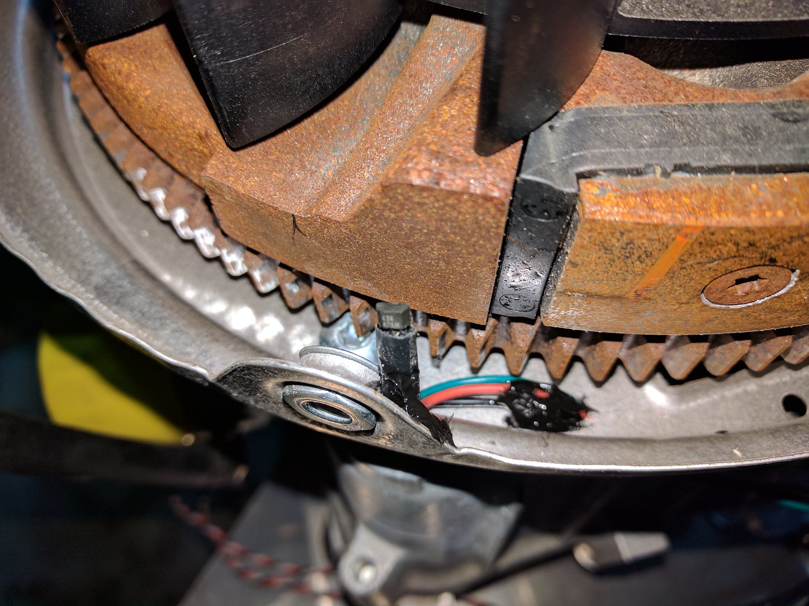 The sensor was also re-positioned to be level with the middle of the magnet.
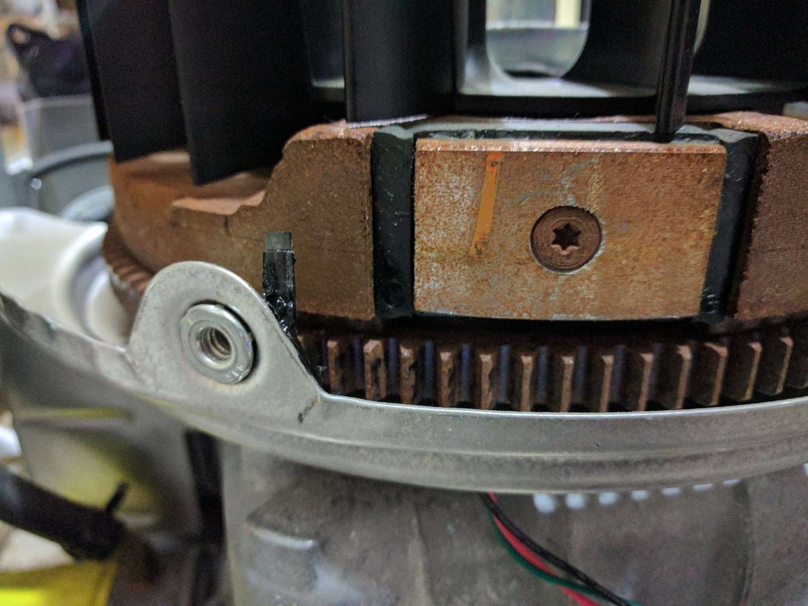 A quick test of the setup was done to make sure the electronics work. The arduino was configured to blink the on-board LED when the magnet was detected. Then the engine was spun by hand to pass the magnet by the sensor. The arduino correctly detected the magnet and flashed the LED each time the magnet passed by.
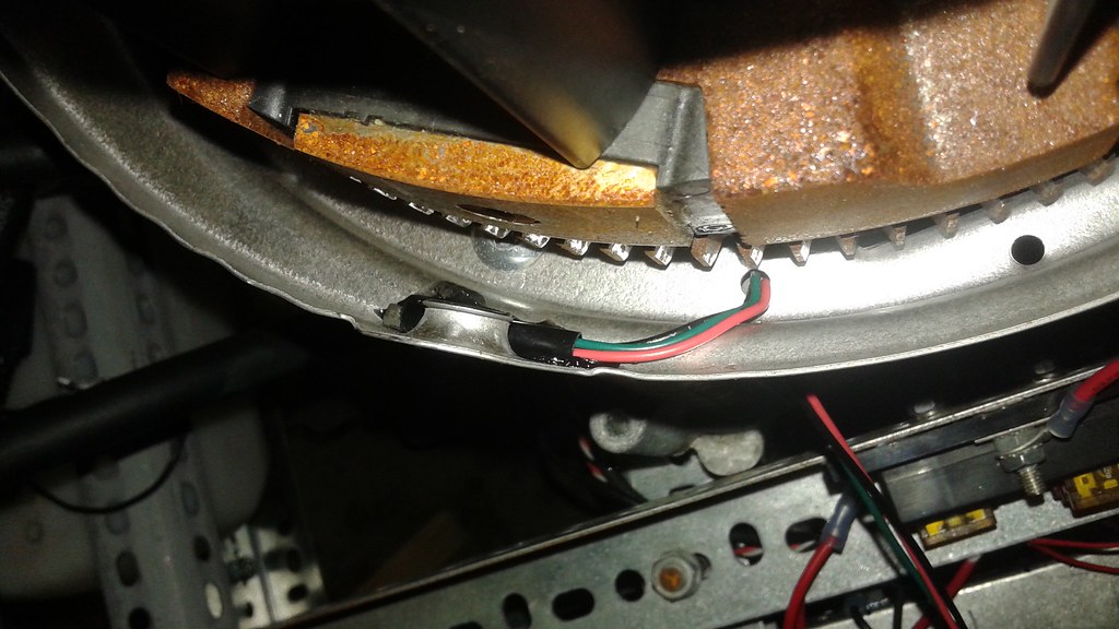 Today the sensor was connected to the Pixhawk ADC port. The wire leads were spliced onto 3 pin Hirose connector and a 10k resistor was added between the power and signal lines.