 colinta
This timer is used to track when the dogs were last fed. The idea is to have four states:
- I just fed the dogs ("green", for 15-30mins)
- Nothing to report ("off" for ~6-8h)
- It's been a while since the dogs have been fed ("red" for ~2h)
- The dogs need to be fed ("red+blink")
I first created a version that was just an Attiny85, a reset button (which, just reset the attiny), and two LEDs. That, and a 9V battery + 7805, and I thought I was good to go. 10 hours later the battery was kaput. So, I learned that microprocessors, even the lowly '85, consume tons 'o' battery power.
I looked into the low-power features of the Attiny, but in my heart I knew that I should really be creating this using simpler IC chips. At some point I learned about making a "8-24h timer" using a 4060 14-stage ripple counter, that was the first clue. I knew I could configure it to, say, turn on an LED at the 8h mark, but I didn't want to change my requirements just to make things simpler... my breakthrough was adding two S/R flip-flops (via a 4013, with the data and clock lines tied to ground).
The various components go something like this:
Ingredients
- 4060 14-stage ripple counter w/ internal oscillator
- 4013 Dual flip-flops, configured as S/R flip-flops (D and CLK pins held to ground)
- 555 configured as an astable multivibrator to make the Red LED blink
- 2 LEDs w/ requisite current-limiting resistors
- SPST N/O button to reset the circuit (debouncing is not a concern here)
- 9V battery
- 7805 w/ the usual 0.1µF and 0.33µF capacitors
- RC circuit for the oscillator
- RC circuit for the 555
- Capacitor to reset the circuit on "boot"
- A diode-logic AND circuit (two diodes and a resistor)
- And a bunch more signal diodes and resistors
Power
Nothing fancy here, just a 9V battery and a 7805 circuit.
Timer
The 4060 has an internal oscillator, so you need only attach a capacitor and resistor to pins 9 and 10, and then hook that up to the CLK pin 11. Once the chip gets power, it'll start ticking, and on a 14-stage ripple counter that means it is counting from 0 to 16,384 in binary. In my case, I wanted 16,384 to be somewhere around the 8-10 hour mark. I found that a 4.7µF capacitor and 100k resistor worked well for that... though, going through the math now, it looks like that should only be a 2h timer... well, I dunno, I know what values I'm using, and I know that the timer starts blinking somewhere between 8 and 10 hours as desired.
Reset
The 4060's RST pin is hooked up to a SPST button and to V+ via a capacitor, so the circuit is reset-on-boot and when you press the "I fed the dogs" button. The Reset circuit is also used to turn off the Red LED and turn on the Green LED.
Green LED
The green LED is powered from the Q output of one of the flip-flops on the 4013. The SET pin is connected to the Reset circuit, so Green turns on when the circuit is turned on and when it is reset via the button. To turn the LED off after a few minutes, I attached Q10 of the 4060 to the RESET pin of the 4013.
Red LED
Similar to the Green LED, the Red LED is controlled via the other flip-flop in the 4013. Instead of being SET when the chip is reset, it is RESET on load, and turned on after many hours.
There's a little more going on here, though. Turns out that in order to get my desired ~6-8 hour point, I need it to turn on when Q12 and Q13 both go high. Rather than add an AND chip, I opted to use diode logic for this. Takes up less space on the board, and I'm not sure but I think it earns more nerd points. Win, win!
But what about when the timer is complete, and I want the Red LED to blink? Three things: I need to turn off the flip flop, I need to disable the timer, and I need to activate an astable multivibrator. Actually, not so hard! Hook Q14 to the 555 power (I used an NPN transistor for that, btw) and connect it to the CLK pin of the timer, and the RESET pin of the flip-flop (there's a diode in there, too, to prevent sinking the CLK signal into Q14 when it is low).
Putting it together
On the breadboard I used a much...
Read more »

 jurc192
 scubabear
 littleBits
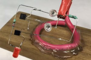
Wow!