 Pero
PeroNow that everything's finally working, I could go on and get some real job done here. For instance, to check out what's worth this little MAX2871 chip. What's the spectral content of the synthesized signal? Is it stable? How much does it vary with temperature? What's its quality factor? I used R&S FSIQ3 3.5GHz spectral analyzer to measure all these properties.
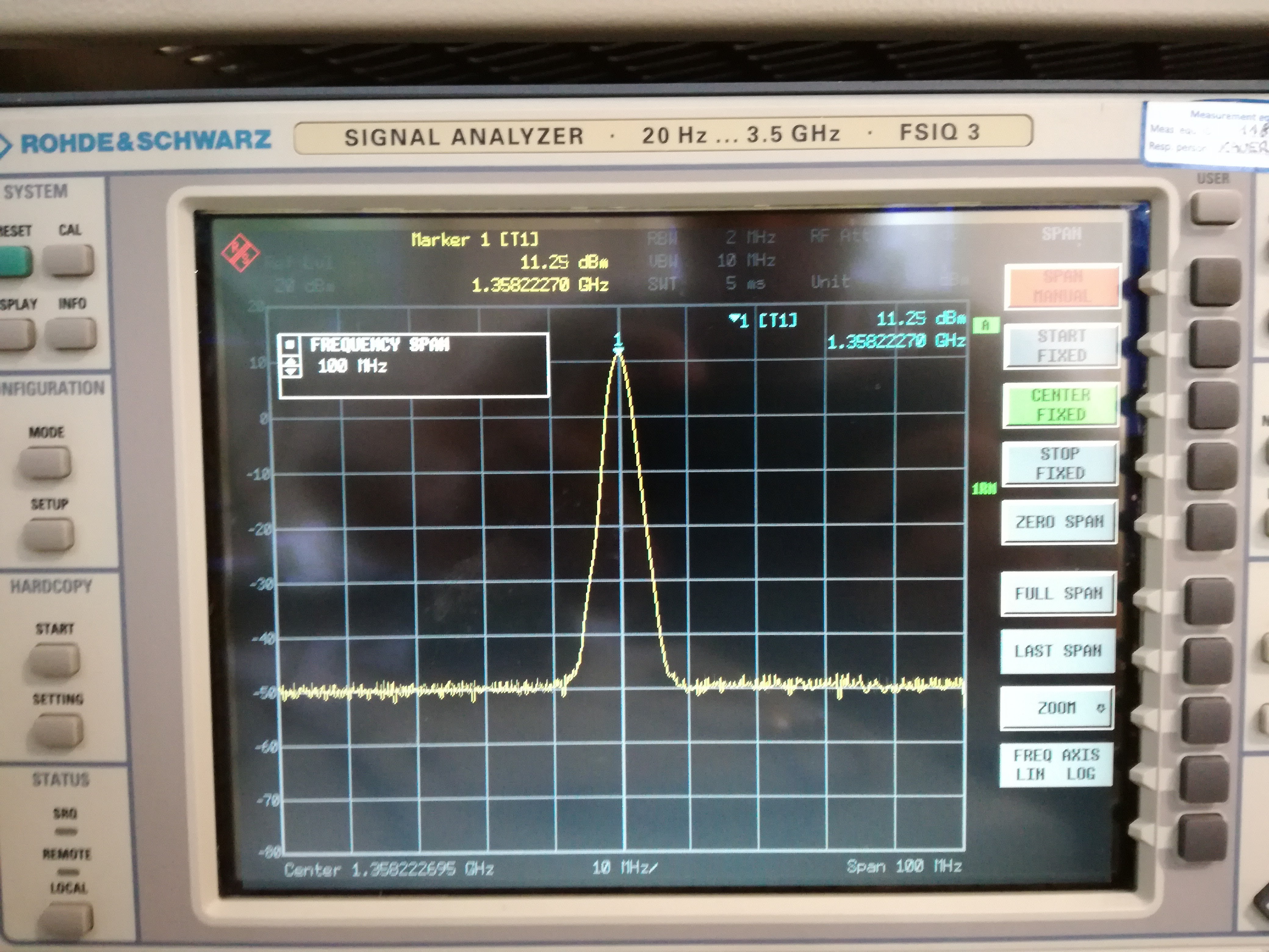
I use my small Arduino program to control the synthesizer ("Basic" example in my Github repo). I can enable/disable RF ports and control the RF output power. Once the transmitter is powered on, I use large frequency span (100 MHz) of the SA to locate the signal. I chose 2 MHz resolution bandwidth to start with. Here we can see nice 11.25 dBm peak at 1.35 GHz (DIVA = 1):
When I reduce the span to 50 MHz, or zoom-in, to be more technical, I observe some funny things (again technical) on the sides of the peak:
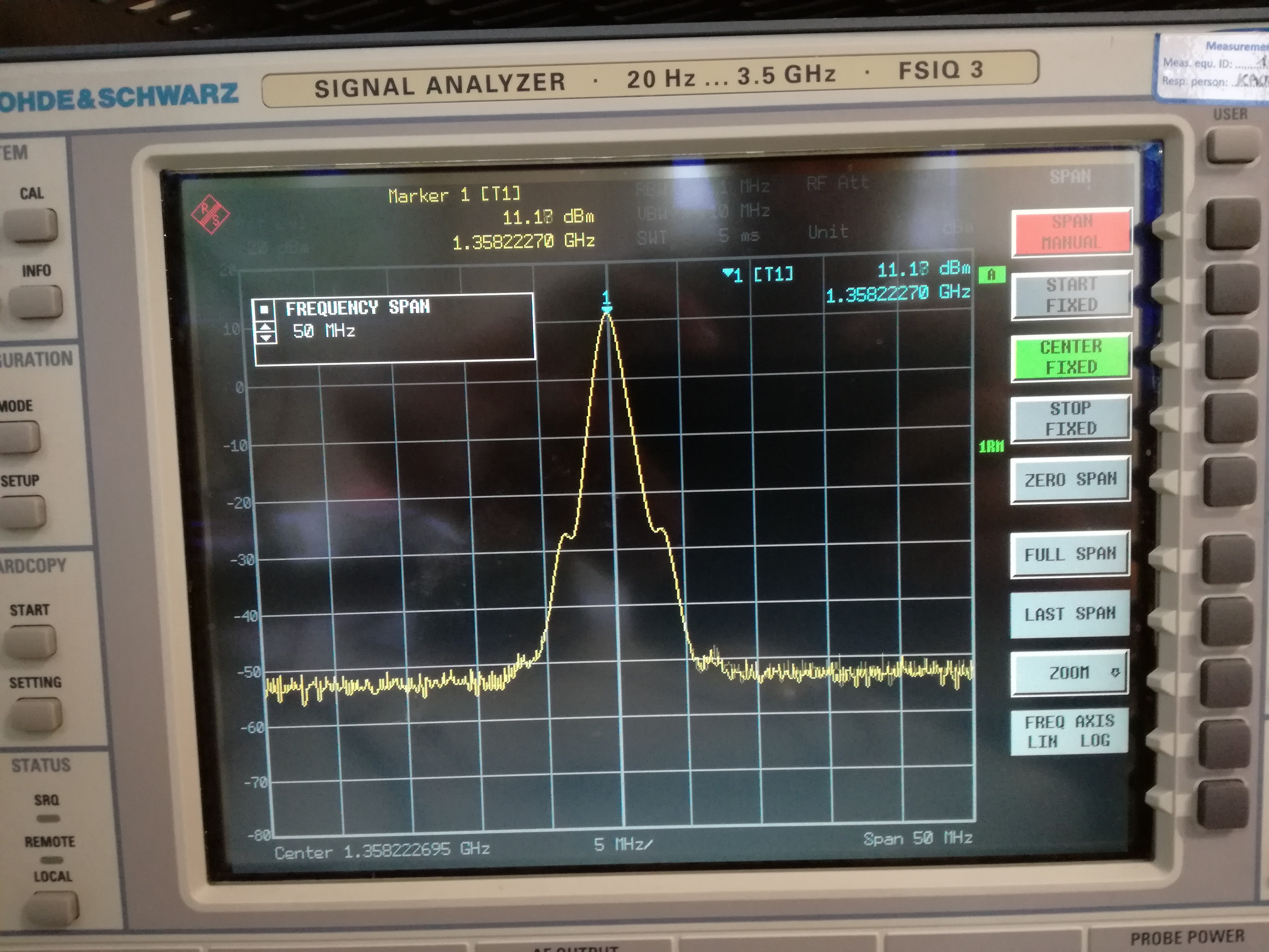
It looks like two small tumors growing on our signal. Further zooming in, we'll see the tumors are becoming real devil's horns:
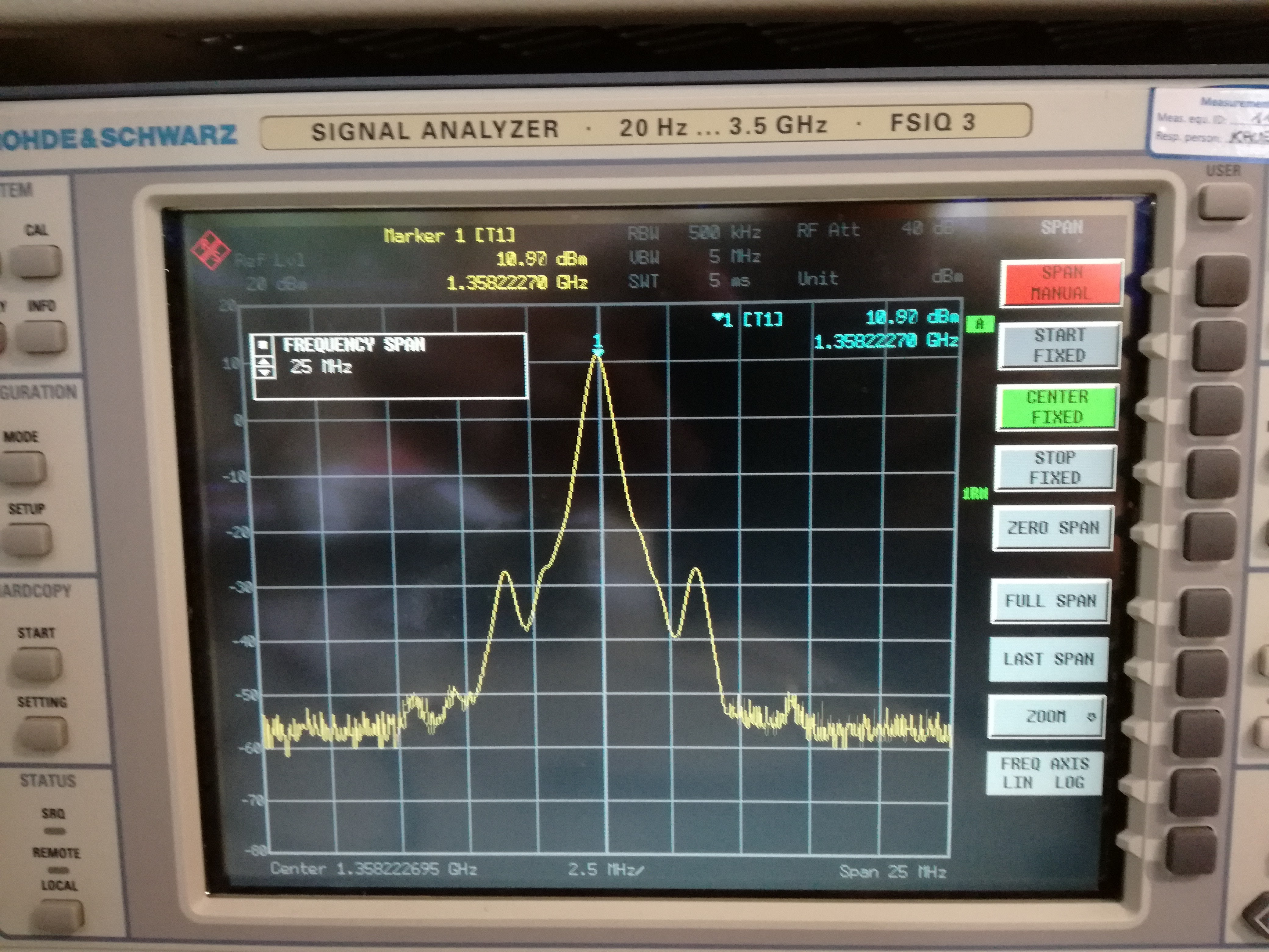
With my frequency span lowered to 12.5MHz, I could see even more peaks unveiling in the spectrum:
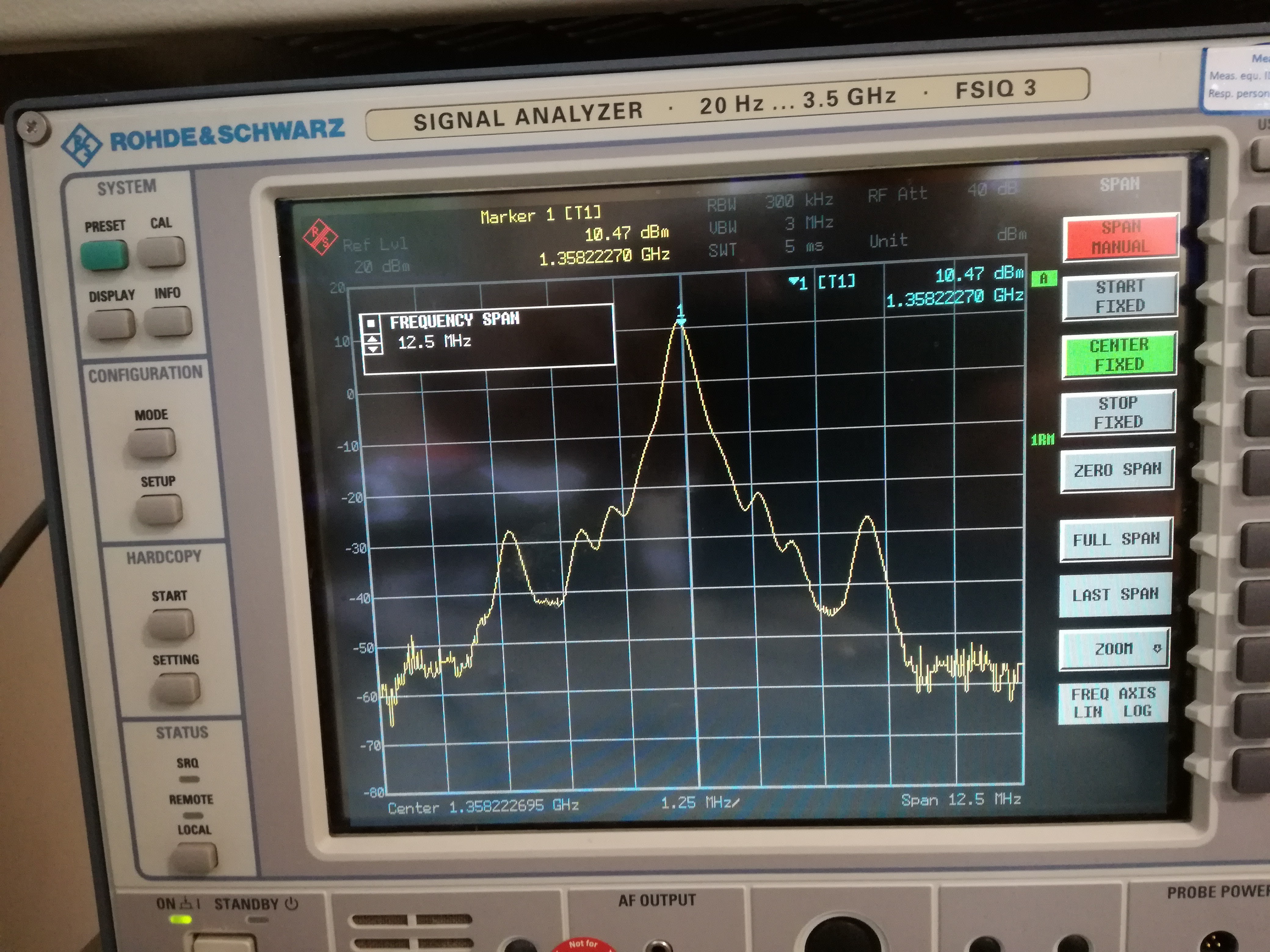
Finally, with span of 6.25MHz, the crystal clear peak turns to be a total spectral jungle filled with side lobes, and multiple order harmonics of some basic frequency transposed to 1.35 gig:
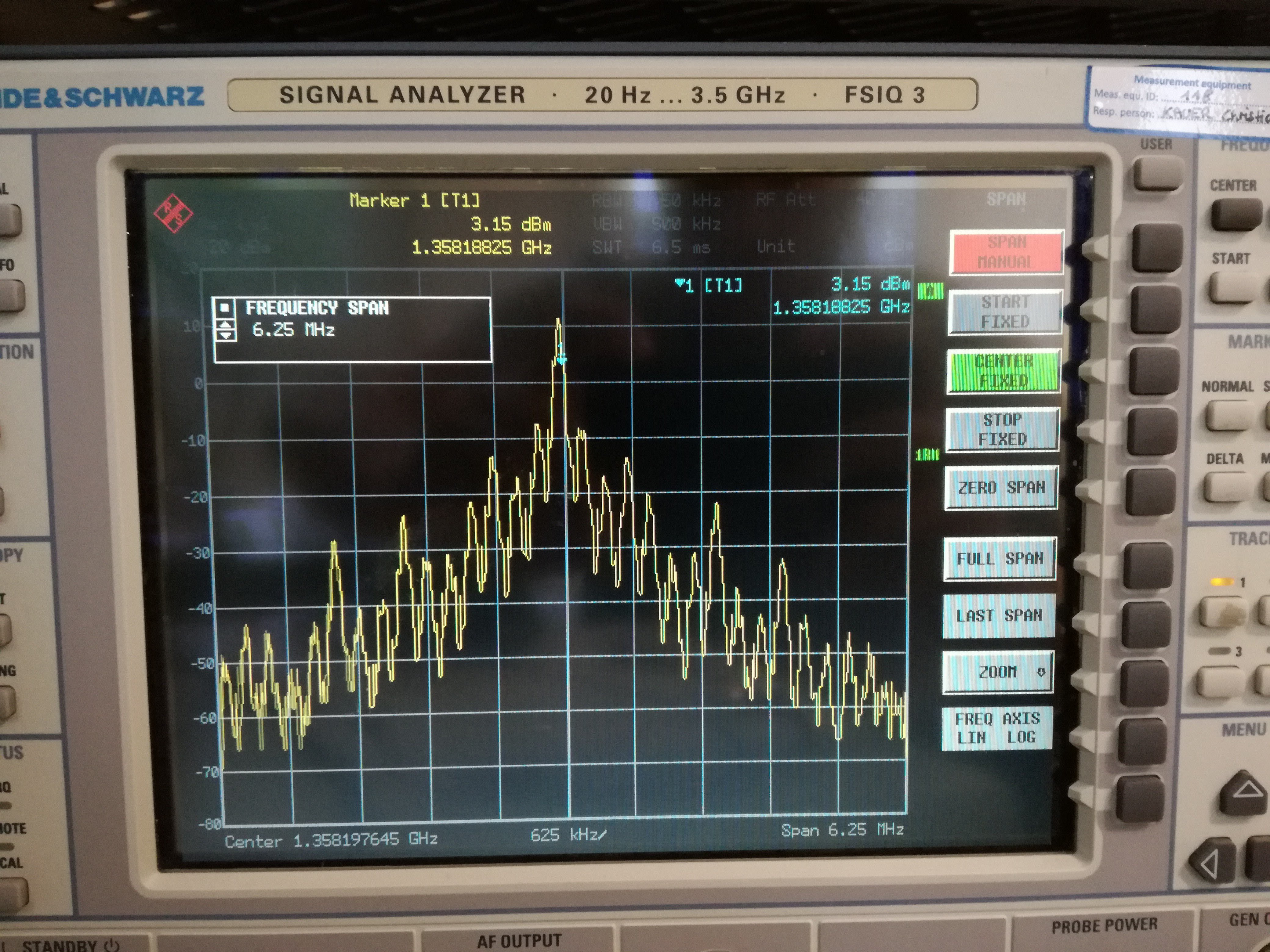
I was expecting that Δf will be around 19.2MHz, what corresponds to the reference frequency of my crystal oscillator. It turned out to be false - the peaks are showing up at irregular distance, hundreds of kHz apart. I can only assume it's some PLL black magic of the MAX chip behind this, like intermodulation products in the chip. Maybe I should start sounding like a professional and address this phenomenon by its name: phase noise. Datasheet specifies it to be -136 dBc/Hz at 1 MHz offset. Since I have division factor N = 135 in the PLL feedback, I can expect additional 20log(135) = 42 dB to the phase noise. It still seams to be much less than what I'm measuring. Could it be chip itself or one more downside of my board (loop filter)?
During these measurements, the frequency drift was barely observable and mostly due to the heating of the chip. I deduct it, as the center frequency only changes when I cool the chip with the tip my finger.
Overall, the synthesizer chip performs well in the frame of what home made, 1st attempt, hobbyist board can hope for. Question that bothers me still is: why is the phase noise so big? why is the spectral content so weird and full of garbage? Why not clean and pointy spike, like I would expect for? Is it caused by the chip itself or by loop filter my board? Is it fabrication trade off for such a wide bandwidth? Questions, questions...I'll start by asking people who made the chip, at Maxim Integrated.
Note on the output power
MAX2871 is said to deliver max 5dBm of power at its outputs. I measure some 11 dBm at the end of my transmitter. Power amplifier TRF37A75 has gain of 12 dB, but programmable attenuator, filters and switches should be 0 dB. In real world that's not the case, so if we're generous, we can say each of them damps 0.5 dB. Together, expected attenuation is (filter, 2x switch, attenuator) some 2 dB. I would add 1 dB for bad soldering on each component (including PA). In total, 5 - 2 + 12 - 5 = 10 dBm, what kinda makes sense with my measurements.
I just want to add that RF power control of the chip worked fine - it really does reduce the chip power in steps of 3 dB.
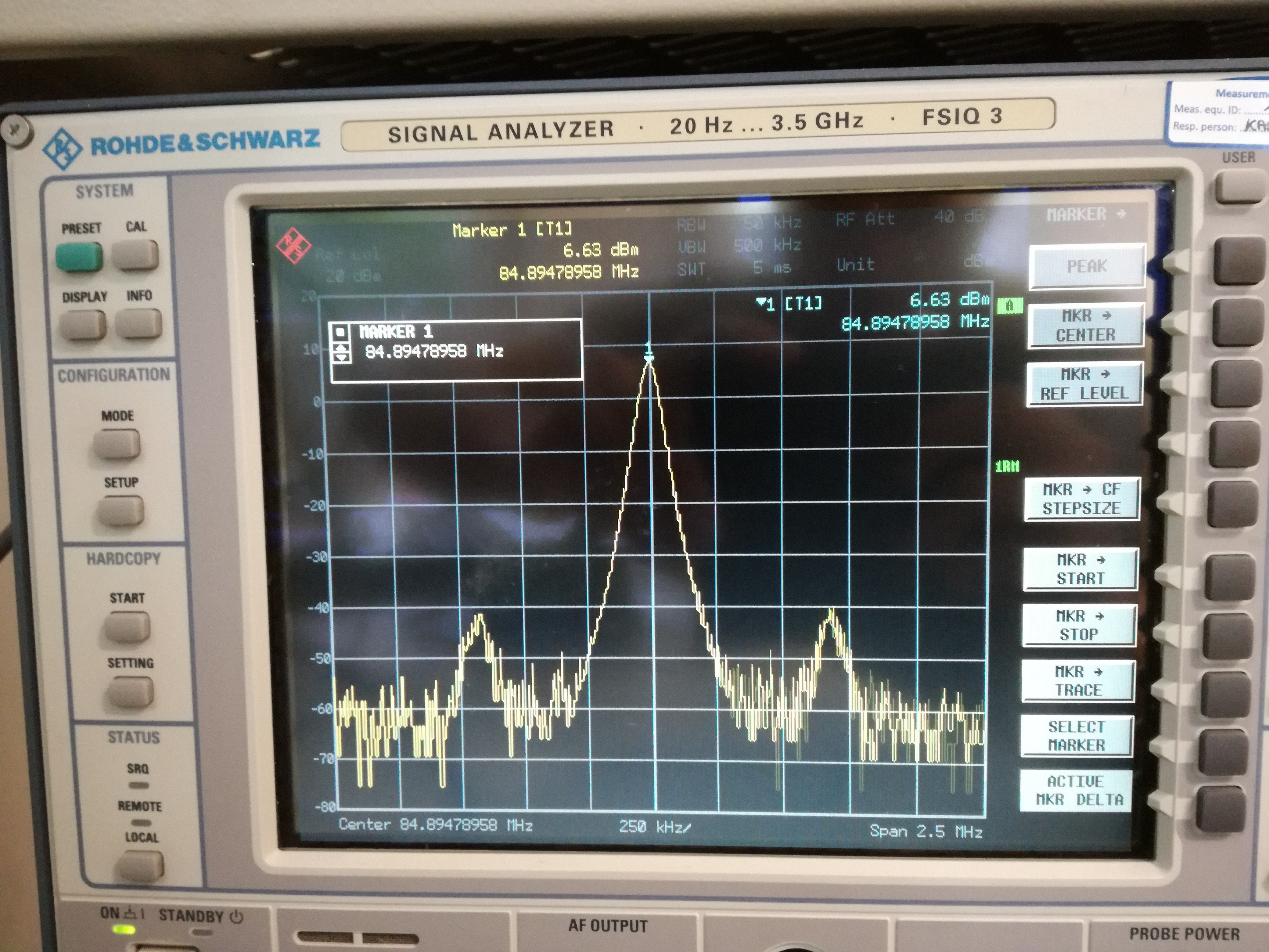
And lastly, I did some measurements at lower frequencies (85 MHz). Total output power in that range was about 6.6 dBm. Hmm, that's weird, all of the components claim to be broadband compatible and I don't expect much loss at such low frequency. Again matter of chip?
Note on the main VCO frequency
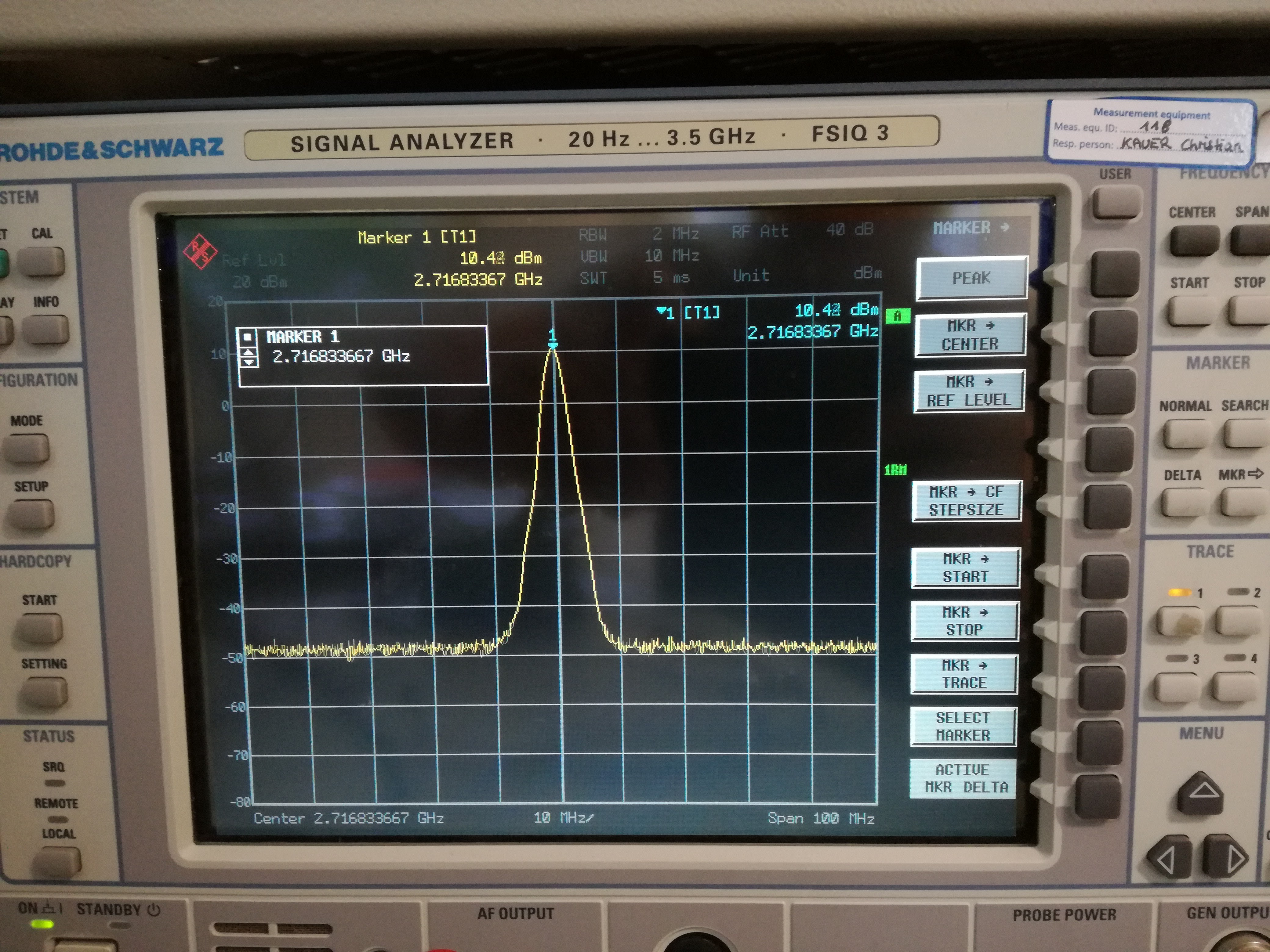
I also wanted to see the max frequency the synthesizer can give (it claims to be 3GHz), so I set DIVA to 0 and powered it on. I measured clean 2.7GHz. Hmm.. where's my 300MHz gone? Bad loop filter? Lying chip?
Note on harmonics
Yes, there are strong harmonics visible on the scope. I just forgot to screenshot them. Luckily, I added filters that will eliminate them from the transmitter output, if necessary.
Discussions
Become a Hackaday.io Member
Create an account to leave a comment. Already have an account? Log In.