 Pero
PeroMAX2871 contains 64 VCOs organized in 4 core blocks with 16 sub bands each. I have no idea how advanced/complex in IC production is, but it surerly sounds impressive. These VCOs are able to cover any frequency between 3 and 6 GHz. The whole span is covered in steps of f_PFD, meaning that f_PFD presents max resolution of the PLL (when it is working in integer mode).
In integer mode, VCO frequency is determined as But, there is certain limit. N can not be arbitrarily chosen and the datasheet boundaries 16 - 65535 is not the only one there. Second boundary is limit of the VCOs: you can not push N f_PFD outside 3 - 6 GHz range. VCO will simply saturate and keep at limits. Another boundary comes from the loop flter. If difference f_VCO/N - f_PFD is higher than cut off frequency of the loop filter, control signal won't be applied and VCO will oscillate with lower limit value.
To demonstrate it, I've put f_PFD to 19.2 MHz (f_REF = 19.2MHz, R = 1, RDIV2 = 0, DBR = 0). I've selected output divider value DIVA to be 32 and 16 ( so I can measure it easier with my SA). Output divider determines final frequency that will be emitted out of the chip:This DIVA factor is actually the one that is responsble for such broad range: if DIVA is 128, we'll have output frequency as low as 23.5 MHz. DIVA can have 8 values, meaning that MAX2871 will synthesize frequency in 8 sub-bands.
As you can see on my schematic, loop filter is simple lowpass RC network with cutoff at 776 kHz. From above disussion, we see that it is necessary that
| f_VCO/N - f_PFD | < f_cutoff.
from there, it follows that limits for N are given by:
N_min = f_VCO,min / (f_PFD - f_cutoff) and N_max = f_VCO,max / (f_PFD - f_cutoff).
For given, settings, expected limits are 162 and 325. When N is within that limit, we can expect linear dependency of the output frequency. Outside this limits, VCO will saturate, or, stay at minimum frequency. This is exactly what you can see on the pics of measured data below.
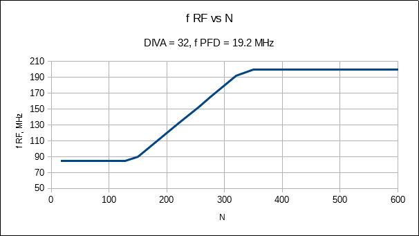
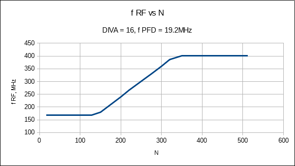
I just realized that I could sum up all the text above simply by saying "f_PFD" is the minimum step size within the given range of VCO frequencies. This what you can read in most of PLL introduction texts. However, I would miss one important thing: not only does f_PFD defines the step size, it also defines, together with loop filter, which steps can be taken. Although N can be as high as 65535, it will have no effect because the VCO will saturate!
Discussions
Become a Hackaday.io Member
Create an account to leave a comment. Already have an account? Log In.