 Russell Kramer
I need to generate an NTSC signal to give the TV. These contain the analog video combined with synchronization pulses and times when the video should be cut off known as porching. I decided to implement this with crystal oscillators and binary counters. I chose a crystal design because it's a lot more stable than Resistor-Capacitor or Capacitor-Inductor oscillators. A tiny amount of instability in a video signal is very noticeable to the human eye.
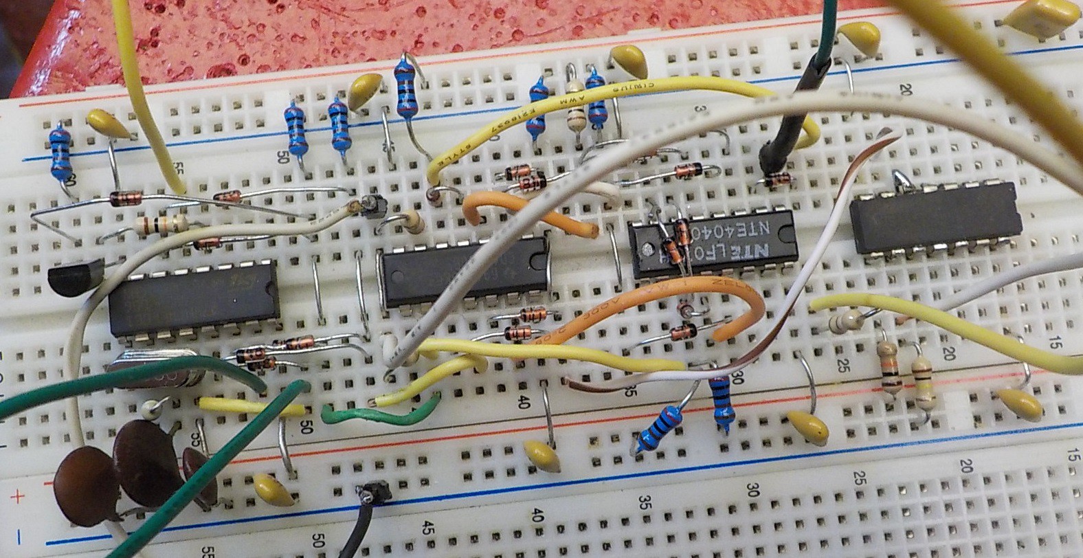
4060 is a binary counter with a built in oscillator driver. 4040 is a regular binary counter.
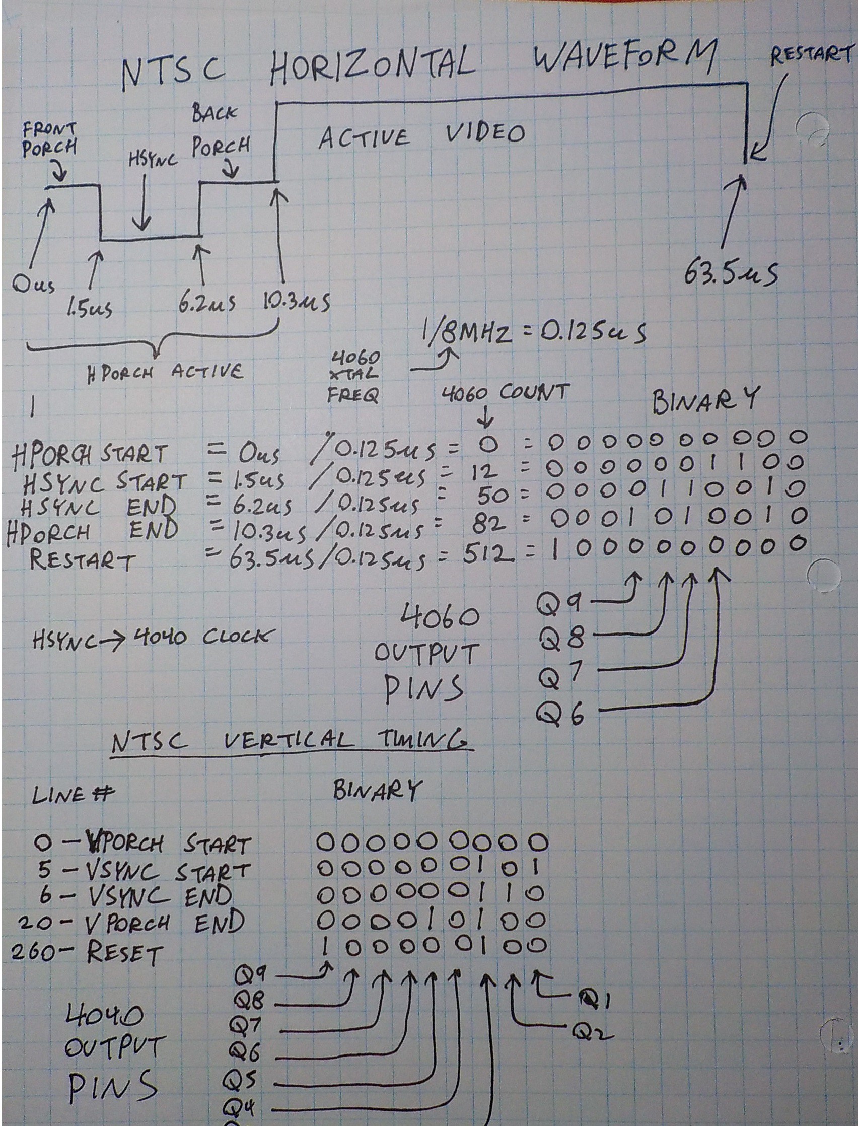
I got the NTSC timing information from this website and decided to use an 8MHz crystal. I ran the numbers with a several different common crystal frequencies and 8MHz required the least amount of logic attached to the binary counters.
My first task was to work out what the binary counter pins would output at the important stages of the NTSC waveform.
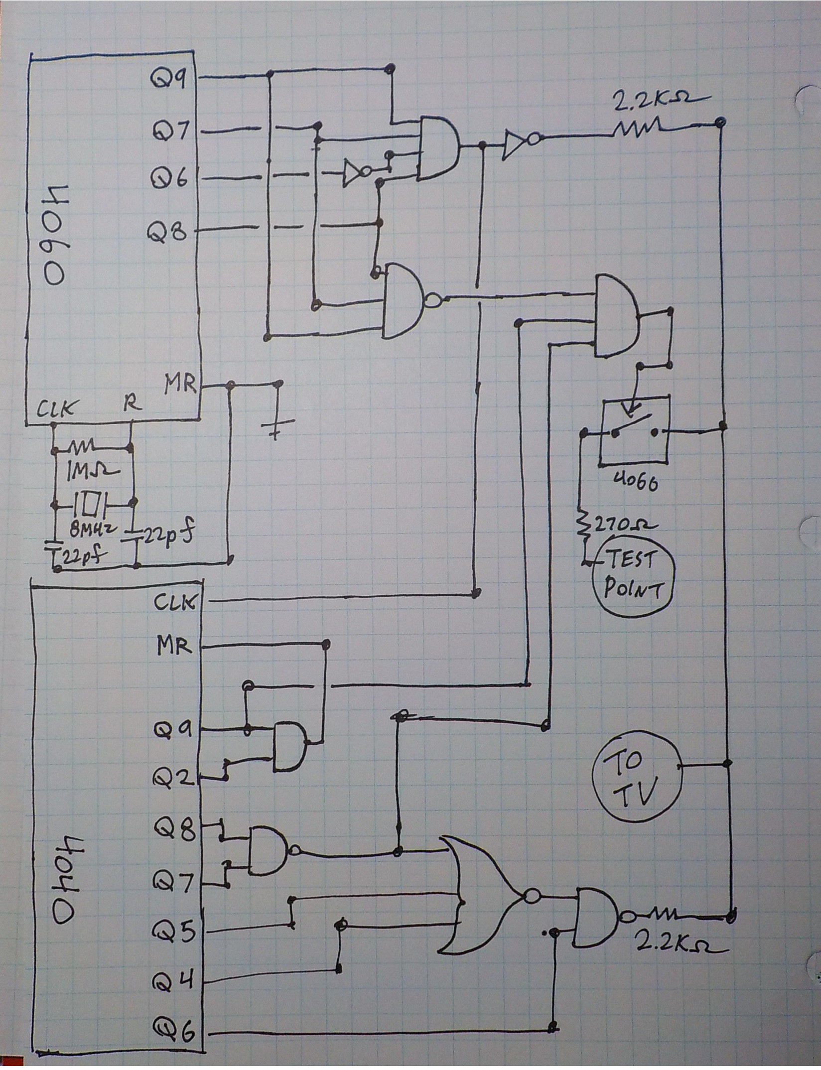
Next I came up with a logic diagram to get the porching and sync pulses to occur when they should. Porching is being accomplished by shutting off the signal through a CD4066 analog switch chip.
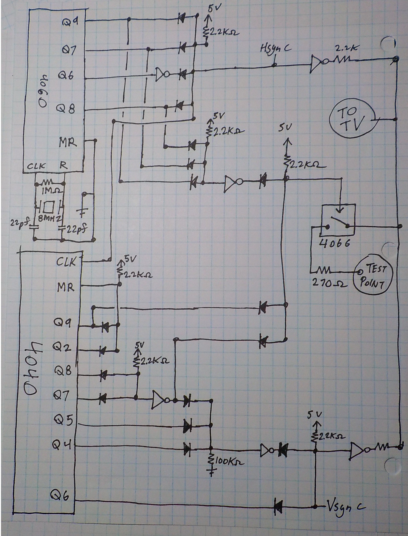
Next I convert the logic diagram to diode logic and inverters (NOT Gates). I like diode logic for projects like this because it makes everything a
lot more inexpensive and compact. It would take three or four gate ICs and a spaghetti of wires to do the ANDs and ORs without diodes. It isn't possible to do inversions like NOT, NAND, NOR with diode logic. All diodes are 1N914.
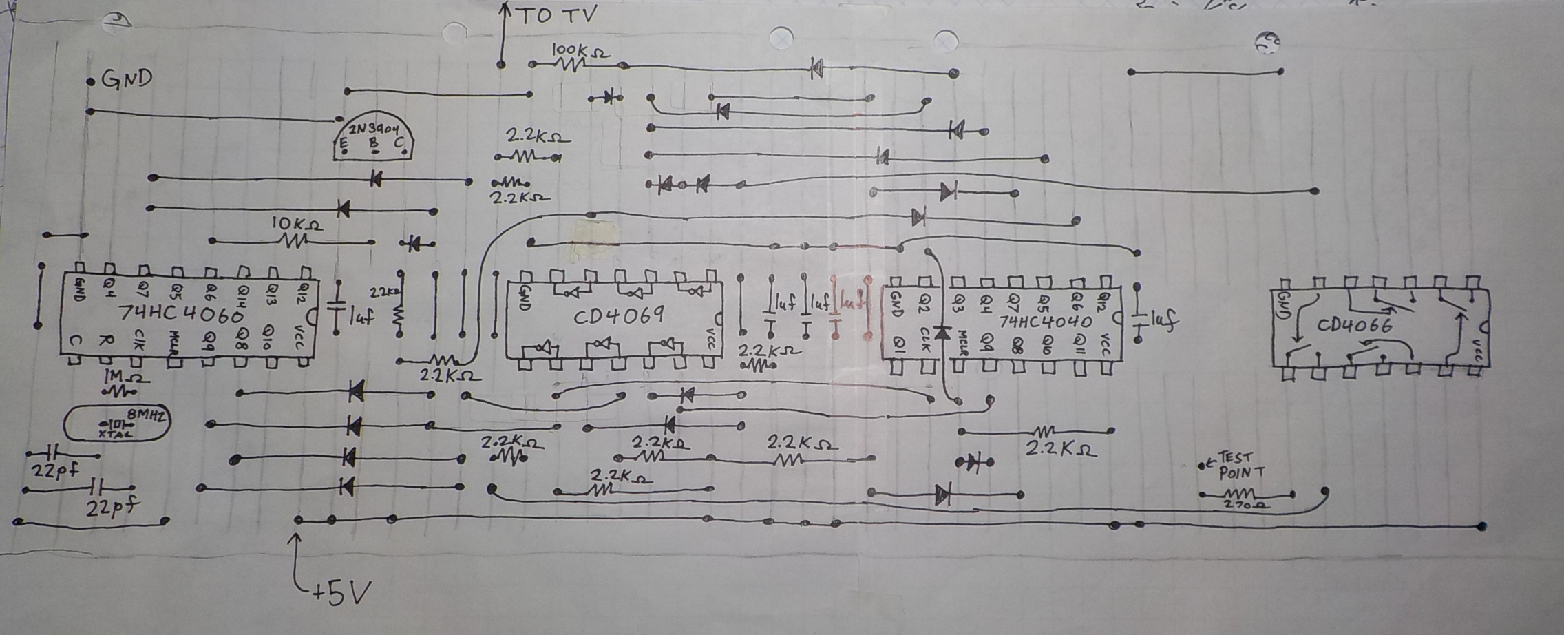
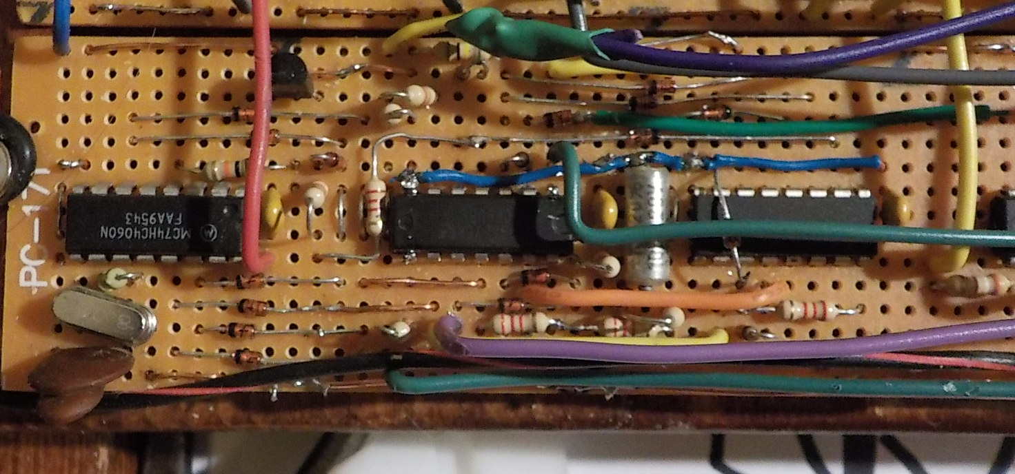
Finally I draw out a stripboard diagram. I'm using "Circuit Test PC-171" stripboards. They have the standard breadboard split down the center, but no power buses on the sides. In my breadboard designs none of the traces are ever cut.
The design called for seven inverters. I used a CD4069 which contains six inverters and a transistor inverter. I didn't want to add another chip just to get one more inverter.
I tested it by connecting the test point to the binary counter outputs. Vertical lines from the 4060 and horizontal lines from the 4040.
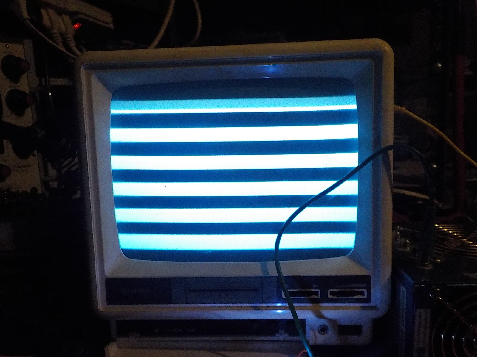
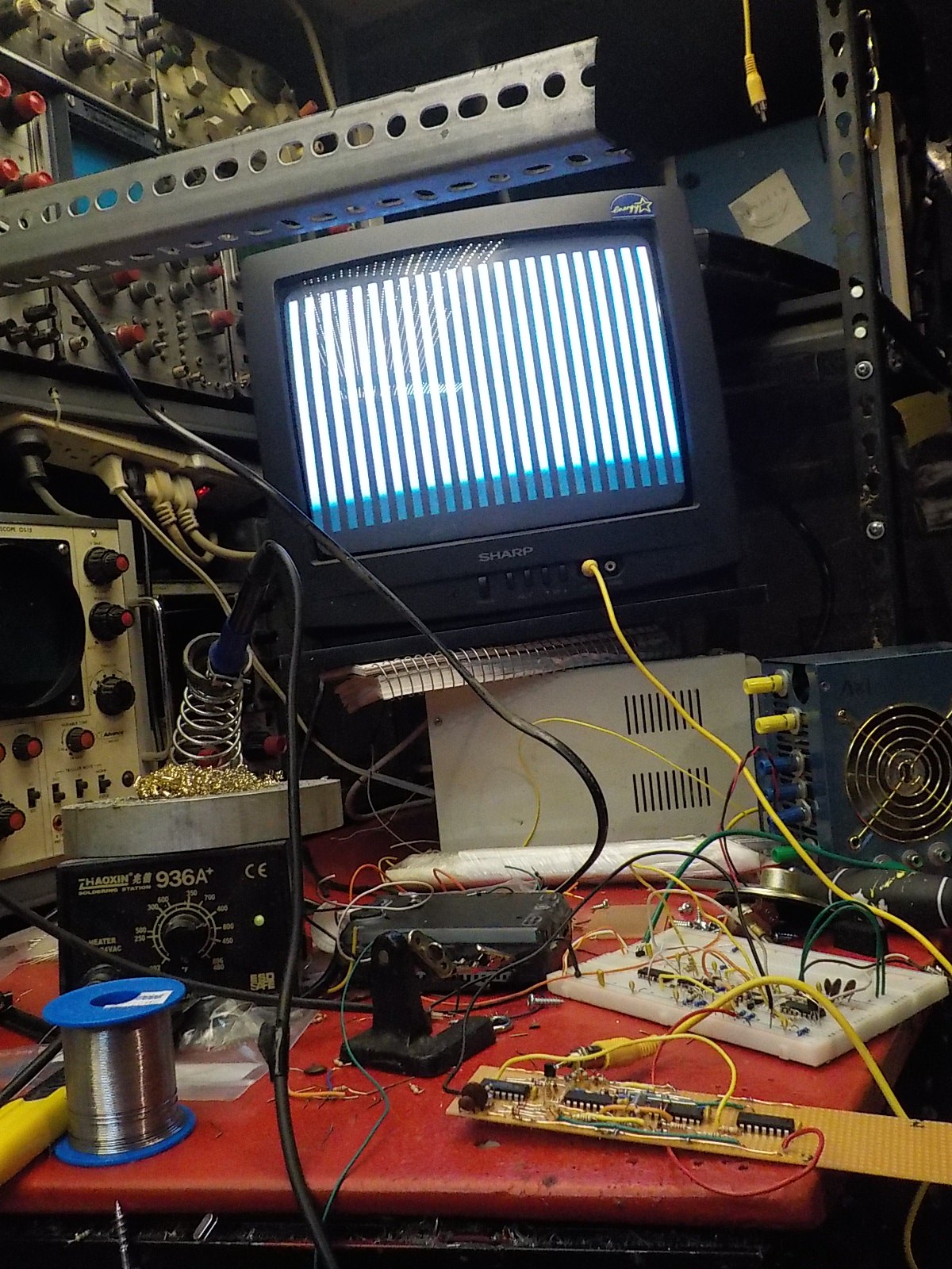
These are some images of the prototype and final builds. There was still some fine tuning going on with the prototype so it doesn't exactly match the final design.
Discussions
Become a Hackaday.io Member
Create an account to leave a comment. Already have an account? Log In.