 Russell Kramer
This is the circuit used to store and access the horizontal positions of the dots. The position of the dots are stored as analog voltages in capacitors and accessed through 1-16 demultiplexers. There are four copies of this circuit. One for each of the four control channels.
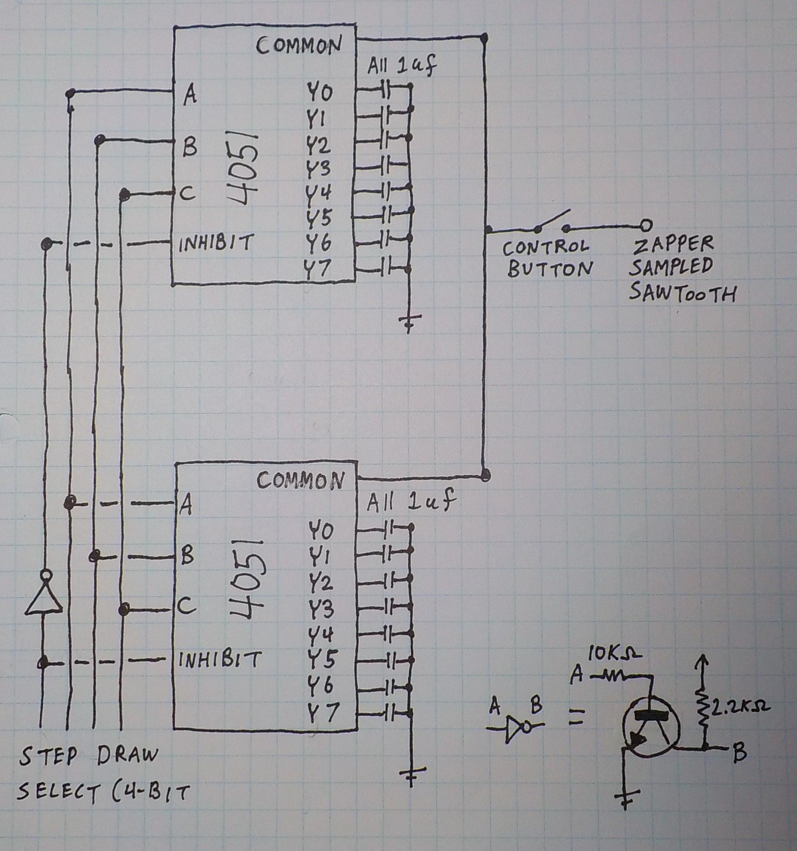
Each circuit uses two CD4051 1-8 demultiplexers so there are eight in total for the four channels. CD4051s have an inhibit pin which is being taken advantage of to get two to work together to produce 1-16. With the inhibit pin active there is no connection between any of the capacitors and the common pin. A NOT gate makes the pair of 4051s alternate between which one is inhibited. Only one NOT gate is needed for the four channels because all four demultiplexers are always given the same address.
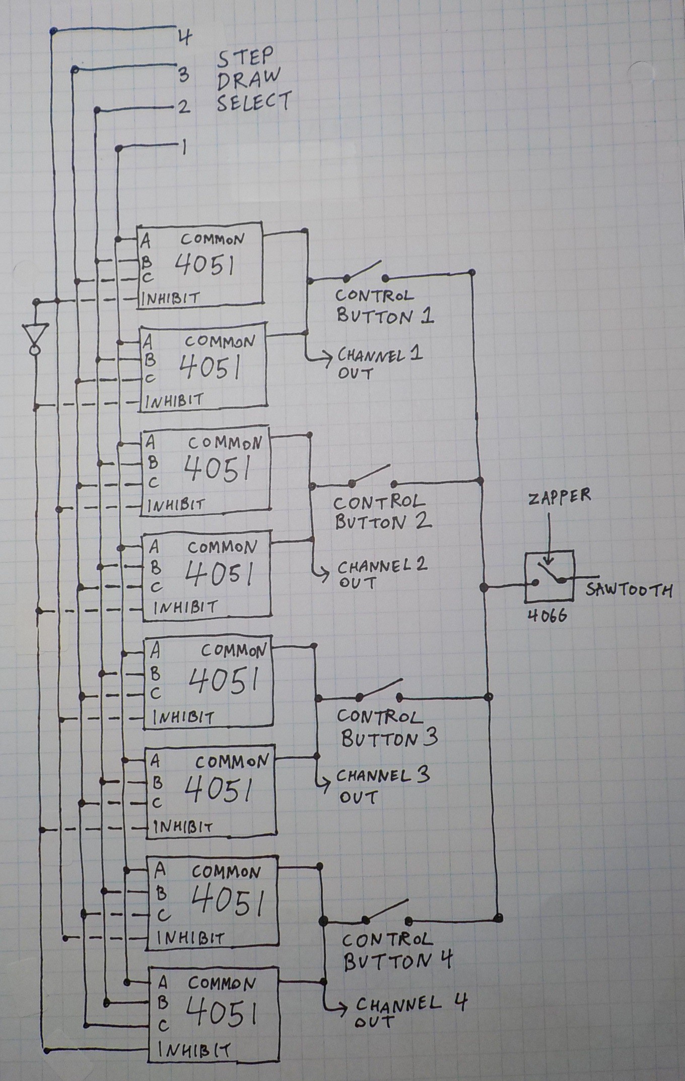
This diagram shows how all four demultiplexers are addressed in
parallel and how the zapper sampled sawtooth is split through four
physical buttons. Capacitors are not shown. Step draw select is the
4040 that counts from 0-15 as the screen is being drawn from top to
bottom.
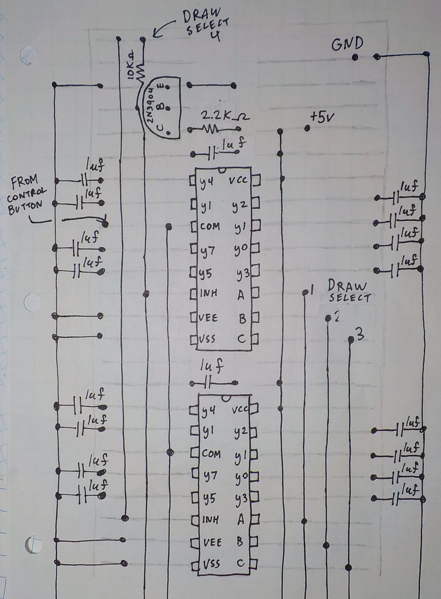
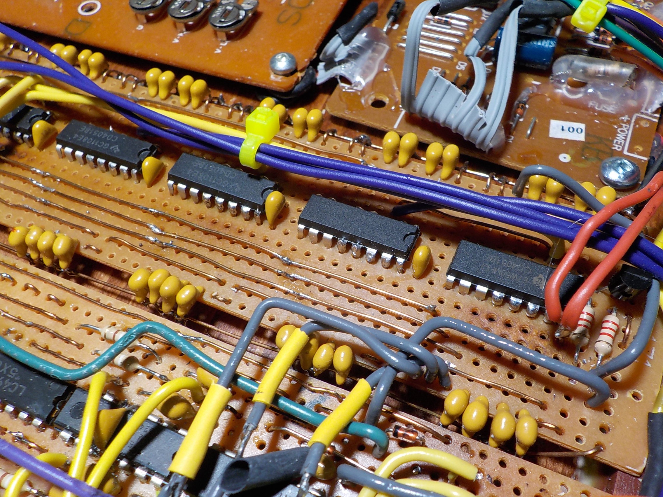
This is the stripboard layout showing the 2N3904 transistor use to produce the
NOT gate for the fourth bit. Only two of the eight 4051s are shown. The placement of the
4051s is replicated three more times. The stripboards I used didn't
have a power bus which was an issue for the large number of connections
to ground required. I soldering a floating piece of bare
copper to either side of the board to be the ground bus.
Discussions
Become a Hackaday.io Member
Create an account to leave a comment. Already have an account? Log In.