0%
0%
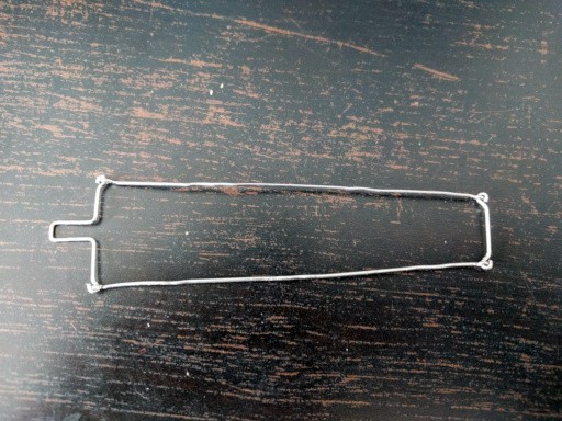
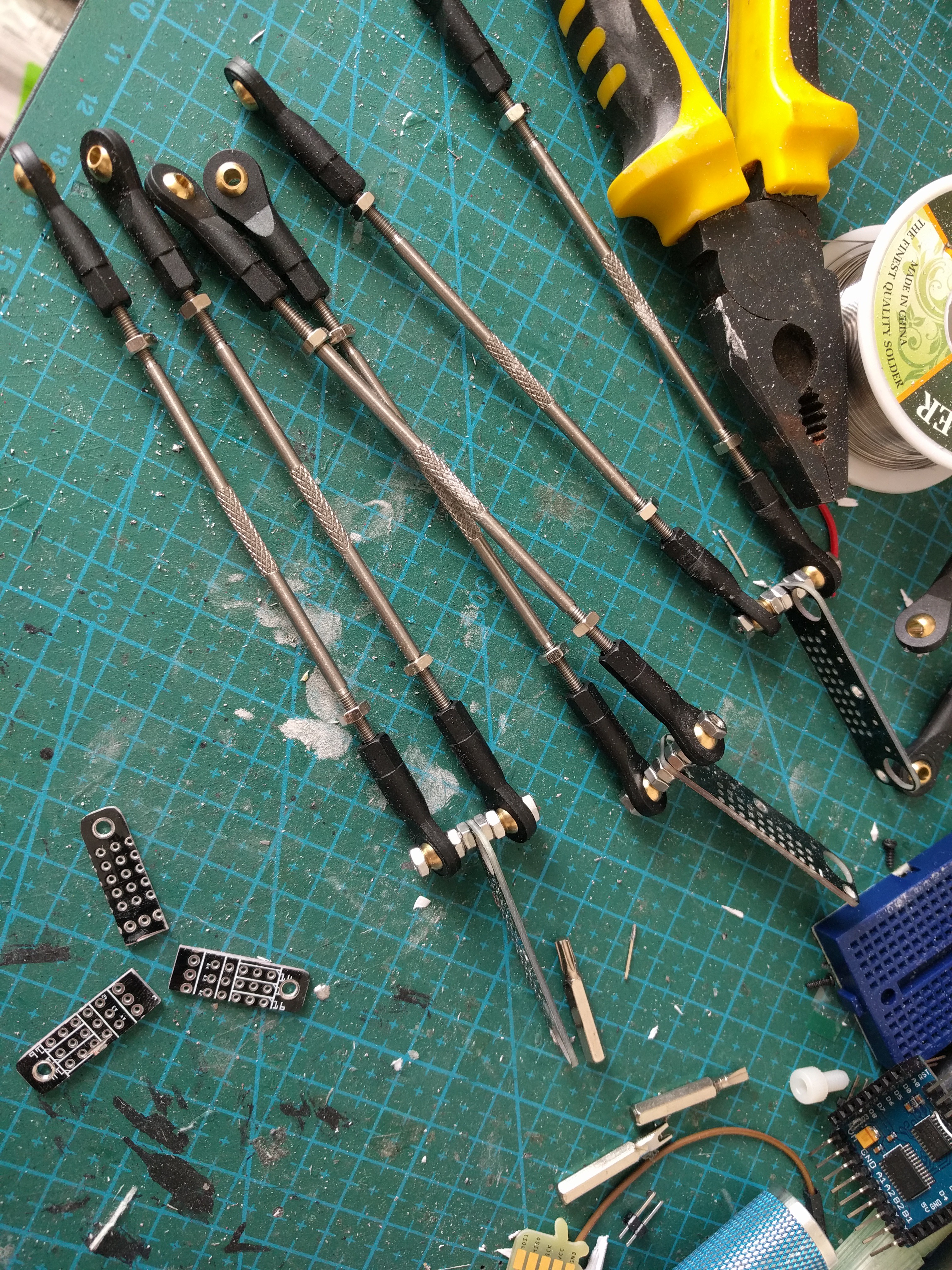
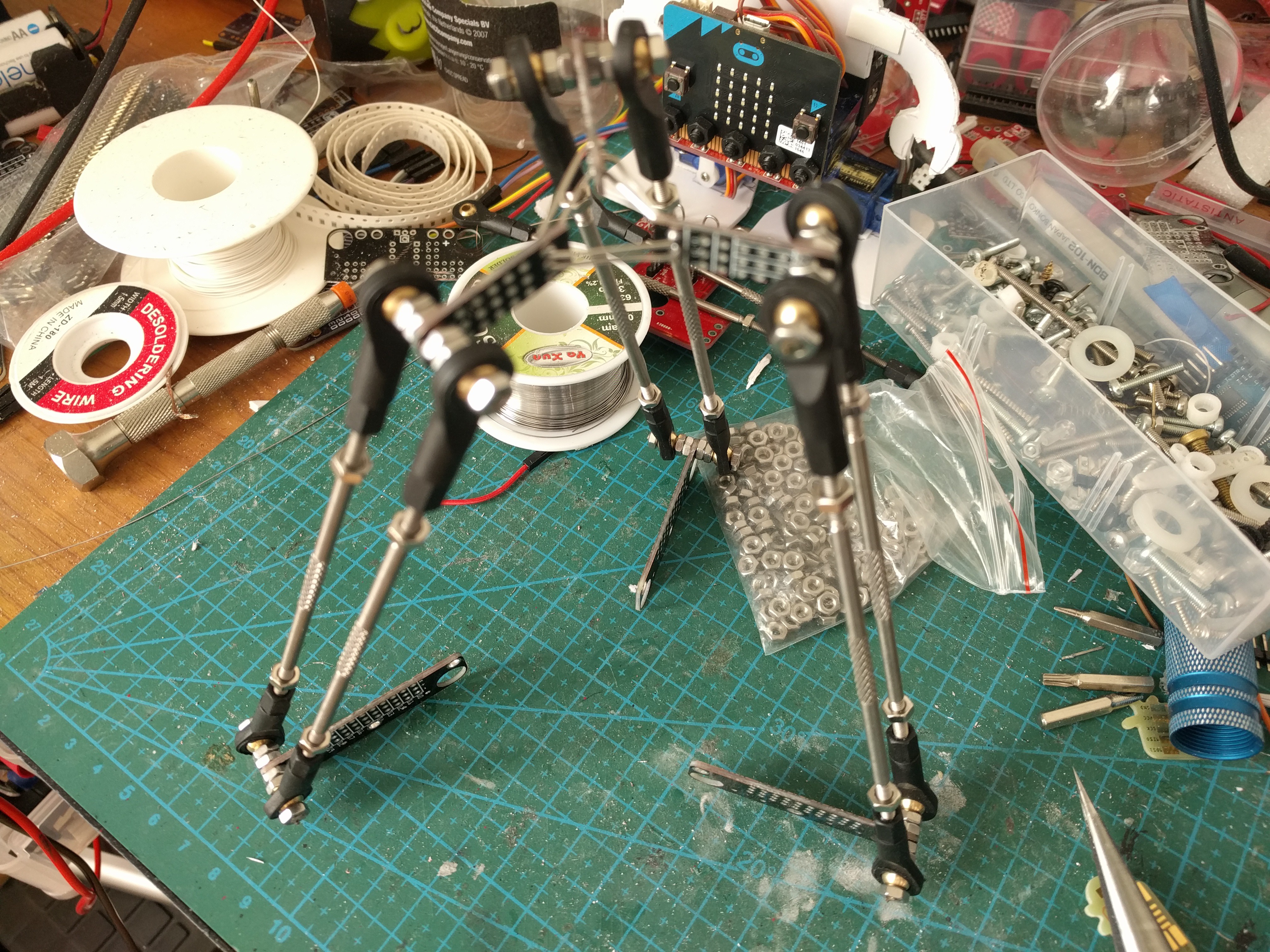
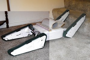
Deltabot
Experimenting with a simple delta robot
 deʃhipu
Become a Hackaday.io member
Already have an account? Log in.
Just one more thing
To make the experience fit your profile, pick a username and tell us what interests you.
Pick an awesome username
hackaday.io/
Your profile's URL: hackaday.io/username. Max 25 alphanumeric characters.
Pick a few interests
Projects that share your interests
People that share your interests

 Duane Degn
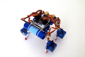
 invent2main
Nice one Radomir.
Put a paintbrush in the centre and paint with it. ;-)