This is the thermometer I purchased, the heart of the system:
http://www.harborfreight.com/infrared-thermometer-93984.html
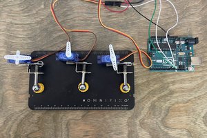
A $50 thermal camera using a non-contact thermometer, 2 servos, and an Arduino
Already have an account? Log in.
To make the experience fit your profile, pick a username and tell us what interests you.
This is the thermometer I purchased, the heart of the system:
http://www.harborfreight.com/infrared-thermometer-93984.html
The gimbal was pretty quick to assemble, though the order of connections was critical and I found I had to take it apart and reassemble a couple times before finishing.
Connecting the servos to an Arduino requires some changes to the wiring. The critical thing is to power the servos with an external source, if you don't the Arduino will brown out when trying to move both simultaneously. I used a 6V external power supply so the servos wouldn't be powered through the USB port.
The pan and tilt motion resulted in a way wider angle than I needed. This could be useful when the thermometer needs to be placed close to the target, but lots more math would be required to account for the angle of motion. From a distance the angular motion can be translated linearly without much distortion.
I considered modifying the servos in some way, probably not gearing but maybe the resistance values of the potentiometers inside so the feedback loop would limit the rotation to a more narrow range. I needed higher torque on another project and used these external servo gearboxes from servo city, those could work but would make the gimbal much larger and more complex.
But, luckily I discovered that servos can be controlled from an Arduino with Microseconds instead of angular measurements. Even at the small angles I wanted the servos to move, microsecond signals allow for 500+ steps of movement. This is possible in the standard library, but I ultimately elected to use the alternate VarSpeed library so I could set acceleration speeds when needed.
This is the code I used to test drawing a frame around the area to be scanned, as a preview before beginning the scan.
// Michael Shaub 1/18/2017
// Based on Sweep by BARRAGAN

#include <Servo.h>

Servo myservoTilt;  // create servo object to control a servo
Servo myservoPan;  // create servo object to control a servo
                // a maximum of eight servo objects can be created

int posTilt = 1500;    // variable to store the servo position
int posPan = 1500;    // variable to store the servo position

int tiltLimitUpper = 1350; //2000;
int tiltLimitLower = 950; //500;
int panLimitUpper = 1750; //2300;
int panLimitLower = 1350; //700;

boolean countDown = true;

int frameCase = 0; //state of the frame sequence
//0=Upper Left Corner, 1=Upper Right Corner
//2=Lower Right Corner, 3=Lower Left Corner

void setup()
{
  myservoTilt.attach(9, tiltLimitLower, tiltLimitUpper);  // attaches the servo on pin 9 to the servo object
  myservoPan.attach(10, panLimitLower, panLimitUpper);  // attaches the servo on pin 9 to the servo object
}


void loop()
{
  frame();
  delayMicroseconds(500);
}

void frame(){
  switch(frameCase){
  case 1: //Upper Right Corner
    if(posTilt<=tiltLimitLower){
      frameCase=2;
      delay(5);
    }else{
      posTilt--;
      myservoTilt.writeMicroseconds(posTilt);  // tell servo to go to position in variable 'posTilt'
    }
    break;
  case 2: //Lower Right Corner
    if(posPan<=panLimitLower){
      frameCase=3;
      delay(5);
    }else{
      posPan--;
      myservoPan.writeMicroseconds(posPan);  // tell servo to go to position in variable 'posPan'
    }
    break;
  case 3: //Lower Left Corner
    if(posTilt>=tiltLimitUpper){
      frameCase=0;
      delay(5);
    }else{
      posTilt++;
      myservoTilt.writeMicroseconds(posTilt);  // tell servo to go to position in variable 'posTilt'
    }
    break;
  default: //Upper Left Corner
    if(posPan>=panLimitUpper){
      frameCase=1;
      delay(5);
    }else{
      posPan++;
      myservoPan.writeMicroseconds(posPan);  // tell servo to go to position in variable 'posPan'
    }
    break;
  }
}
According to this Instructable the thermometer's pins should connect to an Arduino like this:
Here's the sample code I tried first to get some measurements streaming in:
byte n = 0;                            // Interrupt Bit Count
volatile byte pos = 0;            // Values Position Count
volatile byte values[5] = {
  0,0,0,0,0};                                                   // Values to be stored by sensor
byte cbit = 0;                    // Current bit read in

boolean irFlag = false;           // Flag to indicate IR reading has been made
boolean ambFlag = false;          // Flag to indicate ambient temp reading has been made


byte irValues[5] = {
  0,0,0,0,0};                                      // Variable to store IR readings
byte ambValues[5] = {
  0,0,0,0,0};                                           // Variable to store Ambient readings

const int len = 5;                        // Length of values array
const int clkPin = 2;                           // Pins
const int dataPin = 12;
const int actionPin = 5;

void setup(){
  Serial.begin(9600);

  pinMode(clkPin, INPUT);         // Initialize pins
  pinMode(dataPin, INPUT);
  pinMode(actionPin, OUTPUT);
  digitalWrite(clkPin, HIGH);
  digitalWrite(dataPin, HIGH);
  digitalWrite(actionPin, HIGH);

  Serial.println("Type to Start...");                   // Wait for input to start
  while(!Serial.available());
  Serial.println("Starting...");
  Serial.println("IR (C), Ambient (C), Time Since Start (ms)");

  attachInterrupt(1,tn9Data,FALLING);             // Interrupt
  digitalWrite(actionPin,LOW);          // Make sensor start sending data
}

void loop(){


  if(pos == len && values[0] == 0x4C){            // If sensor has sent IR packet...
    for(int i = 0; i < len; i++){                     // Store values to irValues
      irValues[i] = values[i];
    }
    irFlag = true;                               // Indicate IR reading
    pos = 0;
    digitalWrite(actionPin,LOW);             // Make sensor start sending data
  }

  if(pos == len && values[0] == 0x66){          // If sensor has sent ambient packet...
    for(int i = 0; i < len; i++){                   // Store values to ambValues
      ambValues[i] = values[i];
    }
    ambFlag = true;                     // Indicate Ambient reading
    pos = 0;
    digitalWrite(actionPin,LOW);           // Make sensor start sending data
  }

  if(pos == len && values[0] == 0x53){         // If sensor has sent junk packet
    pos = 0;
    digitalWrite(actionPin,LOW);          // Make sensor start sending data
  }

  if(irFlag && ambFlag){        // If successful IR and Ambient reading...
    digitalWrite(actionPin,HIGH);   // Make sensor stop sending data.  Because Timing is weird, I want to ensure the interrupts do not happen during this section.
    word tempword = 0;        // Next 4 lines isolate temperature component of values
    tempword = tempword | irValues[1];
    tempword = tempword << 8;
    tempword = tempword | irValues[2];
    if(tn9Check(irValues)){       // If checksum is valid, print IR temperature
      //Serial.print("IR = ");
      Serial.print(int(tempword)/16.0 - 273.15);
      Serial.print(", ");
    }
    else{                 // If checksum isn't valid, print impossible temp
      //Serial.print("IR = ");
      Serial.print("-273.15, ");
    }

    tempword = 0;         // Isolate temperature component again for ambient
    tempword = tempword | ambValues[1];
    tempword = tempword << 8;
    tempword = tempword | ambValues[2];
    if(tn9Check(ambValues)){        // If checksum is valid, print ambient temperature
      //Serial.print("Amb = ");
      Serial.print(int(tempword)/16.0 - 273.15);
    }
    else{           // If checksum isn't valid, print impossible temp
      //Serial.print("Amb = ");
      Serial.print("-273.15");
    }
    irFlag = false;         // Reset flags
    ambFlag = false;

    Serial.print(", ");
    Serial.println(millis());                           // Print time for logging purposes
    delay(2000);               // Simulate other sensors or code
    digitalWrite(actionPin,LOW);               // Make sensor start sending data
}


}


void tn9Data(){           // Interrupt Function
  cbit =  digitalRead(dataPin);     // Read bit
  if(pos >= len) pos = 0;               // Keep index below 5
  values[pos] = (values[pos] << 1) | cbit;          // Store to values
  n++;              // Increment bit count
  if(n == 8){           // Increment position count based on bits read in
    pos++;
    n = 0;
  }
  if(pos == len){           // If complete "packet" sent, stop sensor from sending
    digitalWrite(actionPin,HIGH);     // again until main loop allows it.
  }
}


boolean tn9Check(byte...
Read more »
Luckily, the thermometer's circuit board has an unpopulated header that's ready for hacking. I wanted to keep my setup flexible so I used an old cable with the right number of wires and soldered a set of header pins onto the board. By making a hole in the thermometer case the cable can be removed anytime.
According to this Instructable the pin out is:(photos to come)
cool idea. If I can't get this one sensor to scan faster, maybe I'll try more. Thanks

Great project. How large of an area are you scanning in 30 minutes? Please keep updating this project since it looks awesome.
And if case anyone doesn't know, always wait for a Harbor Freight sale or use a coupon to get their products cheap.
Thanks! I scanned an area about 8' square and a resolution of 100x100 in 30 minutes. To do a faster capture, I reduced this to 50x50 but didn't see much detail at all. I already added some code to move to the next pixel as soon as a new temperature is detected, so there's no unnecessary delay.
I got some great advice at the un-conference to try storing some or all of the temperatures on the arduino and transferirng them in batches to speed up captures. Can't wait to try that too.

During your presentation at the Unconference you mentioned that your biggest expense was the mount. Have you looked at the servo mounts on Aliexpress? There's a design out there that uses the little servos that come in every starter kit that I've gotten in the past for about 60 cents.
They have beefier ones that resemble the one you were using for about 5 dollars or so.

Details! Details! (they all cried) For me the software explanation was the coolest part. You moved moutains to get this level of quality. Do tell.


Your presentation at the Hackaday Unconference in Chicago inspired me to look into focusing methods for IR sensors, which has helped me immensely (I purchased a non-contact temp sensor on Sunday and soldered in headers to start tests - found that the sensor has a fresnel lens to focus the IR heat signal). Can't wait to further details of your project!!

Great project! Thanks for presenting it at the Hackaday Unconference in Chicago
 Smalls
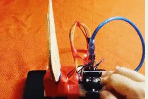
 fullyanalog-programmer
 txdo.msk
 ProgressTH
Perhaps if you used multiple temp sensors, say 4 at a time, that would significantly reduce your scan time.