 Jac Goudsmit
I finally started to do something that I've been wanting to do for over 20 years: use a logic analyzer to figure out how the DCC-175 communicates with the PC. It didn't go so well but I fixed my mistakes. If you want, you can skip this log to go to the next log which will have some juicy interesting stuff (arguably?). If you want to find out how I made a stupid wrong assumption that threw me off for a few days, keep reading.
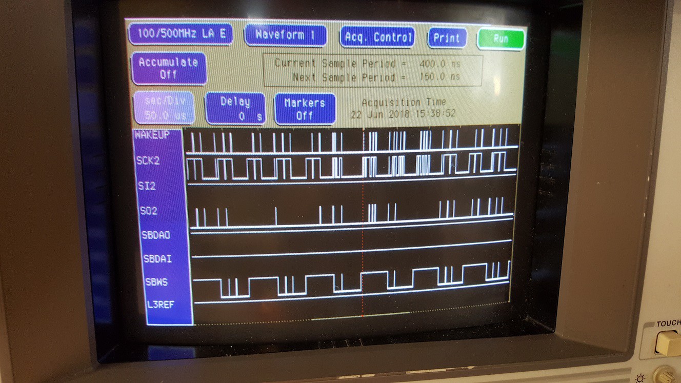
I had attached the pins of the DCC-link cable to the logic analyzer based on the schematic in the DCC-175 service manual. The other end of the cable was connected to my 1999 Dell Inspiron laptop running Windows 98. But instead of the signals I was expecting to see, I got the mess that you can see above. Obviously, that picture makes no sense at all. Lots of spikes, and none of the wave forms look anything like I would expect. It looked like there was a lot of interference, possibly a problem with grounding.
Grab a Hold of This
So I back-tracked what I did:
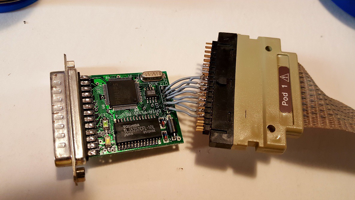
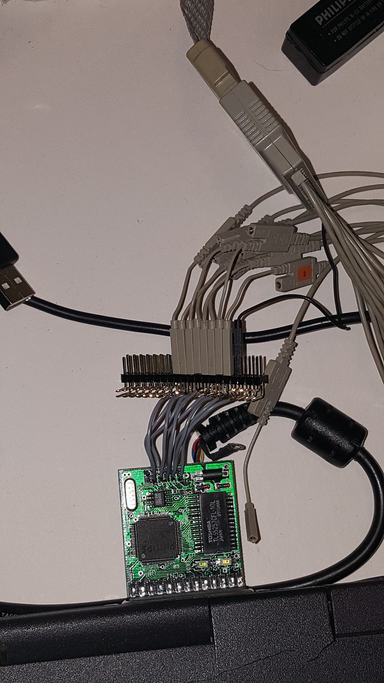
First of all, I had tried to connect the grabbers of the logic analyzer to the right-angle connector that's in the DCC-link plug and connects it to the cable to/from the recorder. Right angle connectors usually have plenty of blank copper and space to clamp the grabbers of the logic analyzer, right?
Well... No. My HP 16500C logic analyzer from eBay is at least 20 years old and most of the grabbers left their best days behind them a long time ago. The header on the DCC-link circuit board uses 2mm spacing (not 2.54mm) and the grabbers are just a little too thick, and they don't grab that well anymore either. And though it looks okay in the picture below, doing my project this way was going to be pretty frustrating with grabbers flying off in all directions all the time.
So I had decided I needed something that would be a lot more sturdy. Maybe I could just make something that I could plug straight into the pod of the logic analyzer?
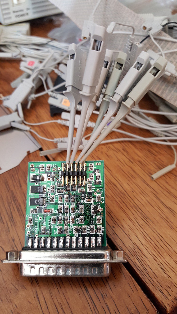
I soldered some wires to a straight male header from my modest parts bin. I kept the wires short to minimize the chance of interference and/or skewed timing readings.
But the pins kept getting pushed or pulled out of the header and then they were a pain to put back.
Let's try again, this time with a right-angle header so the force on the pins is mostly sideways instead of longitudinal, so hopefully that way they won't come out of the pod. That seemed to solve the mechanical issue, but I still got a lot of that interference and even if I ignored the interference, the signals made no sense. I gave up and didn't have time for the project for a few days.
When I came back, I decided to go back to the drawing board.
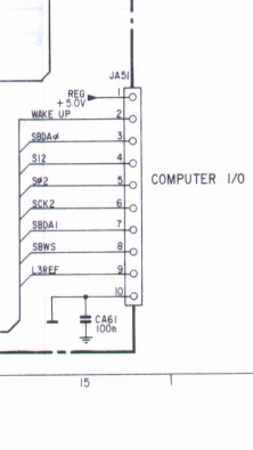
The picture above is the part of the schematic of the DCC-175 that shows the computer connector. But I knew the cable is shielded so the shielding is not in the schematic drawing. Maybe I needed to use that as reference ground? But that didn't make sense, since the DCC-link works fine without the shielding attached to anything.
I started doing some measuring with a multimeter, and the first reading was immediately way off: instead of 5V between pin 1 and 10 on the DCC-link circuit board I measured something that wasn't even close. But that didn't make sense: The LED lit up while the circuit wasn't even connected to anything except the recorder. So it was getting 5V just fine, nothing was broken.
I've had the computer side of the plug open many times since 1995 and I don't even have the cover on it nowadays because there's a coating on it that's changed composition and made it all sticky and yuck. But I never had the recorder side of the cable open until now. I opened it to see if something was loose (and for giggles). Was the ground pin connected to the shield of the cable but not to pin 10, or something? Nope. All the pins of the connector were connected to the cable. The cable is nicely color-coded by the way, and the conductors in the cable was attached in an order that made total sense (if you know the values of the color codes on resistors): black=pin 1, brown=pin 2, red=3, orange=4, yellow=5, green=6, blue=7, violet=8, grey=9 and white=10.
Wait a minute.
Once I saw how orderly the plug on the DCC-175 side was connected, I remembered that I hadn't noticed that kind of order and regularity on plug at the other end.
I had completely overlooked the possibility that the pins on the PC end of the cable might not be connected in the same order as the other end. I guess I've spent too much time in a world where connectors are mostly connected by ribbon cables where a twist in the wire is always obvious. The engineers who designed the DCC-link plug weren't bound to the order in which the signals were connected to the plug, because it was easy to switch conductors of the multi-conductor wire at assembly time.
That explained a lot: Not only was I using one of the signals as ground reference, I also had pretty much all my wires crossed.
| DCC-175 pin number | Wire Color | DCC-link Pin Number | Signal Name |
|---|---|---|---|
| 1 | black | 1 | 5V |
| 2 | brown | 10 | WAKEUP |
| 3 | red | 6 | SBDAO |
| 4 | orange | 4 | SI2 |
| 5 | yellow | 5 | SO2 |
| 6 | green | 9 | SCK2 |
| 7 | blue | 7 | SBDAI |
| 8 | violet | 8 | SBWS |
| 9 | grey | 3 | L3REF |
| 10 | white | 2 | GND |
Order Please!
After I corrected my mistake, the logic analyzer was still showing crappy signals but they made a lot more sense now.
When I read through the manual of the analyzer, I found out there's a small RC filter in the leads between the pod header and the grabbers. Alright, fine. So I can't plug my jig straight into the pod, but I can plug in the grabber header and connect the end to each of my connector without the grabbers. This turned out to be a nice way to keep everything attached while I would play around with the logic analyzer.
Note, nothing is connected to pin 1 (the 5V power supply of the DCC-link from the DCC-175). I don't need to analyze that. So the black ground lead is now correctly on pin 2, and I made sure the rest of signals were correctly configured in the logic analyzer.
Now all signals started showing up rock-solid on the analyzer, and they started making sense too!

All of the signals are now very clear; there's a glitch on the WAKEUP trace in this picture but it's not very important anyway; it obviously just signals to the recorder that a PC is attached and wants to control it. (EDIT: I found out a way to fix the WAKEUP signal later).
I had the analyzer set up so that it triggered on the L3REF signal which is a short pulse to indicate the start of a tape frame, according to the SAA3323 datasheet. The data that's coming out of the I2S bus (SBDAO and SBWS) is what's expected, and the format of the serial data was somewhat of a pleasant surprise; more about this in the next log.
Now that the setup is in a working state, I can get serious with the reverse-engineering project. In the next log, I'll show what I discovered so far and how I'm going to proceed.
Discussions
Become a Hackaday.io Member
Create an account to leave a comment. Already have an account? Log In.