 Jac Goudsmit
After the fiasco that I described in the previous log, where I had connected all the wires in the wrong order, I finally saw some usable data on the Logic Analyzer that made sense. In this log, I'll describe the signals for those who are playing along at home, and maybe haven't read the datasheets and service manuals (or haven't read them as many times as I have).
First of all, let's fix a mistake in the schematic in the DCC-175 service diagram:
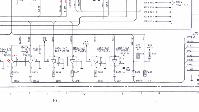
In the schematic on page 10, near the bottom, there are six tri-state bus buffers TC7W125FU and TC7W126FU to connect the DCC-link cable to the internal electronics. The two buffers that you see on the left of the fragment above, each have one end connected to the PC connector and one end to the I2S bus between the DRP and SFC chips. But in the original schematic, both these buffers are drawn in the same direction (i.e. as if they both send the same data to the computer) which makes no sense of course.
The signals "SBDAI" and "SBDAO" are obviously abbreviations of "Sub-Band Digital Audio In" and "Sub-Band Digital Audio Out", so QA54-2/2 is clearly drawn in the wrong way direction: it's used as an input, not an output. Also, the pin number towards the top of the symbol in the schematic was wrong; it was 2 but it should be 3. The PCB layout on a different page (not shown here) confirms this. I fixed the drawing above and marked the fixups with two red arrows.
About That I2S Bus...
I2S ("Inter-IC Sound", or I-Square-S) is a serial protocol that was developed by Philips Semiconductors (now NXP) as a standard to let components transfer digital audio to each other. Usually these components are chips that are connected via PCB traces or short wires inside a device such as a CD player or DCC recorder.
The bus usually consists of a bit clock signal, a word clock signal, and a data signal. Depending on the application, the transmitter or the receiver may generate the clocks.

The bit clock determines the speed of the bits, and the most significant bit of the data is usually transmitted first (the data is big-endian). When PCM data is transferred, the data is encoded as a 2's complement signed value of up to 32 bits. The word clock is used to switch between the left and right channel: Low is left, High is right. The word clock runs at 1/32 the speed of the bit clock, and interestingly it switches between high and low one bit-clock-time before the first bit of the word is transmitted and received. This may not sound like an easy way to do things, but it is. It makes it much easier to deal with differences in propagation time.
I2S is used a lot in DCC recorders. And not only for 16 bit or 18 bit PCM audio. The SFC and DRP exchange PASC data via an I2S bus too. The bit clock for the PASC connection always runs at 768kHz; the PASC signal only uses half of the bandwidth of the I2S bus: only the first 16 bits of each 32 bit word is used (this is documented in the SFC datasheet). The word clock for the PASC I2S bus is used to indicate whether bytes 0 and 1, or bytes 2 and 3 of a longword are transported. An extra line L3REF is used to indicate the start of a PASC packet.
The L3REF, WS, and SD signals of the PASC I2S bus are available on the DCC-link connector of the DCC-175. The L3REF and WS lines are always outputs, but the SD line is split up into SBDAO and SBDAI depending on whether the recorder expects PASC data from the computer (for playback or recording from file) or not. But there is no bit clock. What gives?
Since the PASC data rate is always 768kHz and since it's always generated by a crystal (even when the recorder is recovering data from tape!), it's not essential to put the bit clock on the cable. The clock can be easily recovered by using the WS line to control a PLL. Or even easier: the PC side of the cable can simply use its own clock and counter that uses its own clock that's "close enough" and use WS to reset itself every 64 bit times (the WS clock runs at 1/64th of the frequency of the bit clock). The timing and format of the sub-band I2S bus is pretty well documented in the datasheets.
We're going to ignore the I2S bus for most of this project because there's basically nothing else to reverse-engineer about it. But let me mention one more thing that might be important later on: Tape frames and PASC frames are not aligned. PASC frames can even have various sizes depending on the sample frequency. So there's no expectation that whenever there's an L3REF pulse, there's a beginning of a PASC frame. There isn't. The PASC decoder doesn't know (or need to know) how the data is framed on tape; it uses the sync pattern FF FF FF FF to find the beginning of a PASC frame.
Analyzing the Synchronous Serial Port
There is almost no information about what the Philips/Marantz engineers put into the uPD78058 microcontroller that the DCC-175 uses to control all the DCC chips. But the datasheet of the microcontroller does have some information about how I/O pins P20, P21 and P22 can be configured for synchronous serial I/O, as they did in the DCC-175.
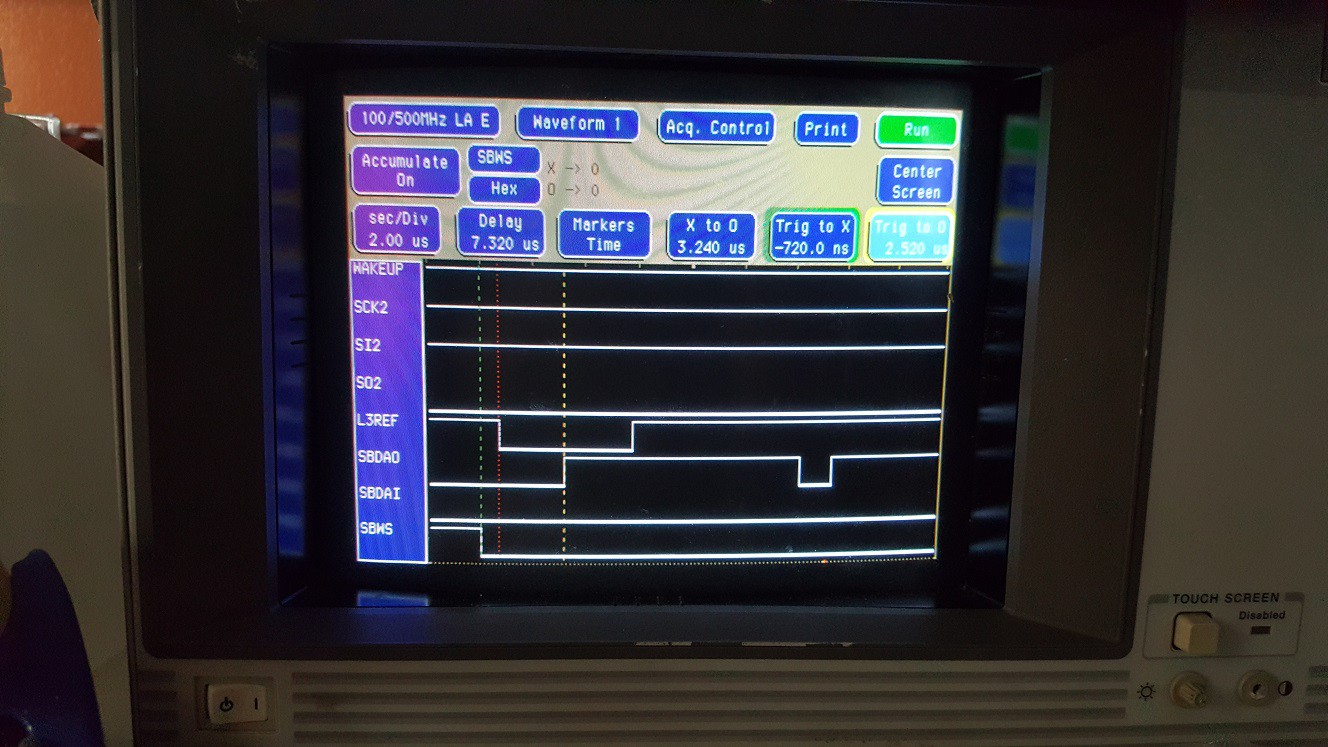
I expected that the serial communication would be sort of like a regular serial port with a clock line. I thought the serial clock would probably be running all the time, and the PC as well as the recorder would use the clock to put data on the input and output, and it would be up to me to interpret what the commands were, and how data such as the Table of Contents would be formatted. But when I connected the DCC-link to the analyzer, I noticed that SCK2 (the serial clock) was hardly ever running. For example in the picture above, SCK2 is not active. So how can the computer send commands and receive updates from the recorder?
The answer was an interesting surprise.

The microcontroller in the recorder and the PC communicate by exchanging fixed length packets of 32 bytes: each little block on the SCK2 time line in the picture above is 8 clock pulses and there are 32 of them. When I kept the analyzer running, it looked like the data coming out of the recorder on SO2 was pretty much mostly the same for each packet (the recorder was in STOP mode).
This might not sound like a big deal but this actually answers a lot of questions about timing, possible ordering of commands and responses, timing, synchronization etc.
Clearly, the recorder determines when it needs to do an update; it doesn't even matter how often this happens. The chip in the DCC-link cable can easily recognize the start of a packet by measuring the time between clock pulses. During an update sequence, the recorder microcontroller sends a status update to the PC, and at the same time receives a status update from the PC. From a software point of view, this makes things really easy: When some part of the software (either in the PC or in the recorder) needs to make a change, it can update the 32 bytes in memory that are transferred during the status update. The actual status update can be a timer interrupt handler on the microcontroller and I wouldn't be surprised if the chip in the DCC-link cable completely takes care of exchanging the information; the PC software probably updates its information at its own pace, with help from the printer port and 4-bit, ECP and EPP protocols.
This is great news, because it gives me a clear direction for what the next step should be. I'm going to use a Propeller on a breadboard and use it to connect to the DCC-link, while it's also connected to the PC and the DCC-175. Then I'll write some software that listens for the 32-byte packets and records the data that goes in both directions. And the nice thing of a Propeller is that I can probably record the PASC data at the same time, and either store all the data on an SD card or simply stream it to another PC via high-speed RS-232-TTL. Then I'm going to see if I can make heads or tails of the serial data.
Discussions
Become a Hackaday.io Member
Create an account to leave a comment. Already have an account? Log In.