 Jac Goudsmit
The other day, I wanted to do some work on this project again after it had been put away for a while. But to my surprise and disappointment, the DCC-175 that I was using for the project before, had completely stopped working. Normally when you push the Play button (or Rewind or Fast Forward), a DCC-170 or DCC-175 shows a message on the screen saying "Power On". But the screen stayed blank.
This was depressing, because I got this DCC-175 a few years ago, after my first 175 stopped working in pretty much the same way. I couldn't find the problem in the first one, and I was afraid I would have to start looking for another replacement on eBay, and they are getting really rare. But then I thought: Maybe I should try connecting it to the computer and power it up that way? As you can see below, that idea wasn't totally successful but also not a complete failure.
The power-on animation that gets quickly preempted by the Power Off message is actually a good sign: at least the microcontroller is still working; there must just be something that keeps it from starting when you try it without computer.
Troubleshooting with Redundancy
My friend Ralf ("Dr. DCC") suggested exchanging the top PCB of the DCC-175 with a (known working) PCB of one of my DCC-170s. The DCC-170 and DCC-175 are very similar, and all the electronic differences are on the top PCB. Everything else is exactly the same between the two portable recorders, except for some minor mechanical differences like the opening in the back side for the computer port. Exchanging the top PCB would narrow the problem down so I'd be able to tell if the problem was on that PCB or elsewhere.
That was a good idea! There was only one problem: I had 5 portable recorders (2x DCC-175 and 3x DCC-170) and as far as I knew, none of them was in working condition. I decided "now" would be a good time to find out what the actual status of each of them was.
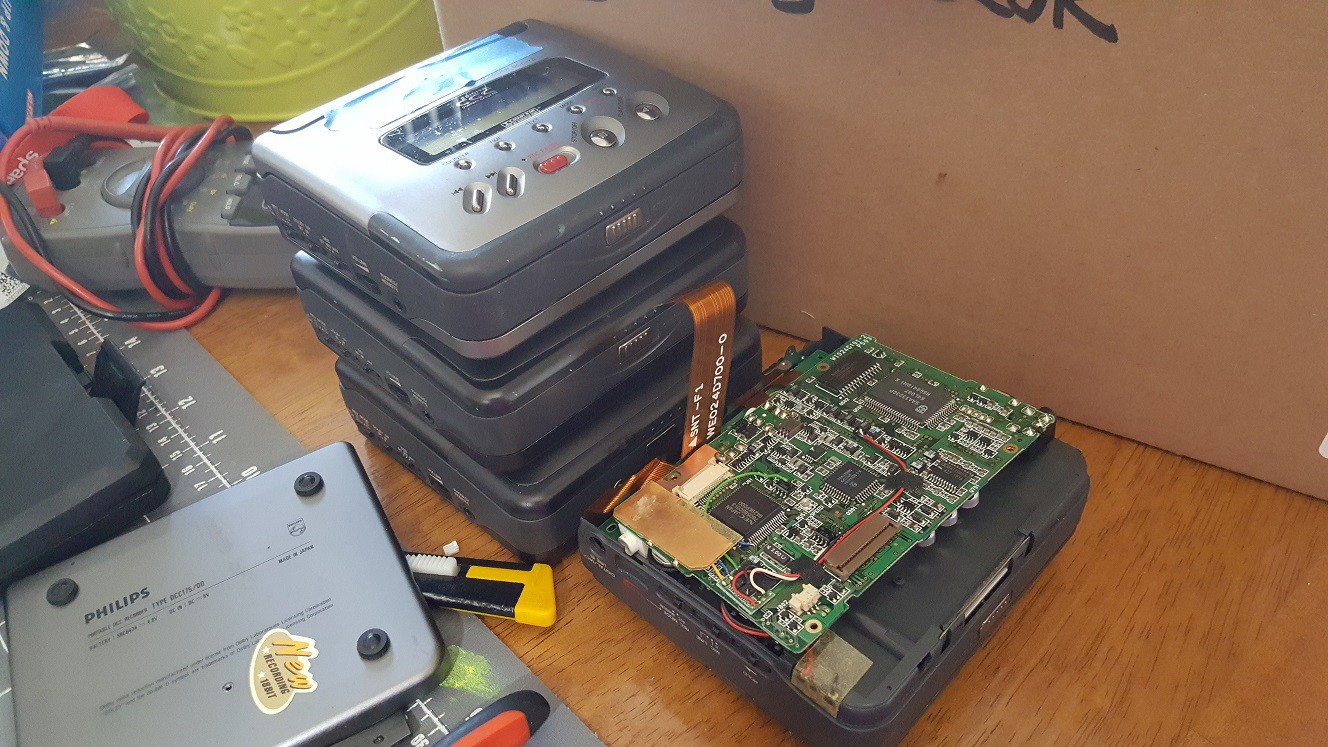
It took me all evening to open each recorder and test which parts of which recorders were still good. I even went through the tedious task of inspecting the belts of each recorder, which is difficult because you have to desolder the motor, solenoid and detection switches, and if you're not careful you can break things and your recorder will never work again. I won't bore you with the details but the end result was that I found out that:
- The top PCB of the recently deceased DCC-175 worked fine when mounted in one of the working DCC-170s. Awesome! That meant that it would definitely be possible to get the 175 working again, even if I would have to replace the bottom PCB with another one from one of the 170s, and therefore lose one of my DCC-170's in the process.
- The top PCB of that DCC-170 didn't work with the recently-deceased DCC-175 chassis (at least at first) but worked great on its own chassis.
- The top PCB of my old, first DCC-175 (bought on the first day that it was available, in November 1995, which I believed to be unfixable), also worked on the chassis of a DCC-170! That means that if the "main" DCC-175 really does go bad, there's a good chance that I can still make my old DCC-175 work.
- After I inspected and cleaned the switches of the mechanism in the "main" DCC-175, it worked again too!
I couldn't get all recorders to work, because I stripped a screw in one of the DCC-170s, making it impossible to take it all the way apart (my Dremel and I would have to take care of that later), and because the belts or electronics in two DCC-170s were bad. Also, the PCB's of my old DCC-175 are in bad shape because I desoldered and resoldered them onto and from the mechanism so many times that some pads have come loose. But it looks like I can make all of my portables run again with some patience and a couple of new belts.
Saying No to Frankenstein
When I couldn't get the DCC-175 to work by itself but was able to make the top PCB of a 175 work with a chassis of a DCC-170, I considered making a "Frankenstein" style combination of the two. This is a picture of the (working) combination.
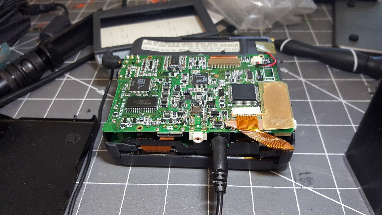
I decided against this, because first of all, it would be quite a bit of work: The top PCB of a DCC-170 fits in a DCC-175 chassis, but not the other way around, so to make a "DCC 172 1/2" combination I would have had to put the bottom PCB of the DCC-170 into the DCC-175 chassis. But besides that, it would also be a wrong thing to do; it felt like deleting two important items in my collection to make one thing that would only benefit me. And it would benefit no-one else.
I'm glad that eventually, after I put the DCC-175 together again, it started working again, just as spontaneously as it had stopped working. Weird! I looked through the service manual of the DCC-170 to learn more about the bottom PCB. There's not really much that can keep a DCC-170 or DCC-175 from starting up. I started writing an article about it but then I noticed the service manual already kind of has the information in the form of a troubleshooting flowchart:
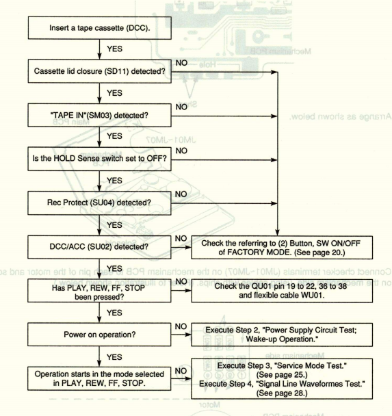
The flowchart doesn't mention that if the lid-closed switch or tape-in switch or hold-switch is not working correctly, you can't power the recorder on. That also means that if the top PCB is not connected to the bottom PCB and the lid PCB, it won't start. Good to know!
The bottom line is: The PCB on the bottom of a DCC-170 or DCC-175 contains the read amplifier, the write amplifier and the motor control circuits. Besides the switches that sense the recorder's status, and let the user operate the recorder, there's nothing that keeps the system from starting. So I guess that's what fixed my problem with the DCC-175 too: all I did was make sure the switches worked, and that made my recorders work again. Yay!
Back to Work!
Alright, I guess that means I should get back to the task of writing some software to analyze the traffic that goes back and forth between the computer and the DCC-175, especially over the synchronous serial port. My main problem there is that I don't have much space for a project like that. As you can see in the next picture (which doesn't even have the main computer in it!) it takes up quite a bit of space and it's not a surprise that my wife doesn't want that on the coffee table for anything but a short time. EDIT: I made a solution for that, see the next article.
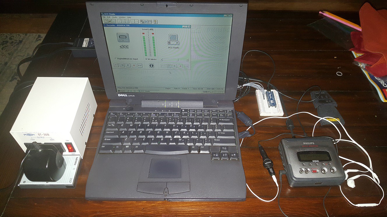
I use the original 220V power supply that came with my first DCC-175 because I trust it better than other 110V wallwarts that I bought since I emigrated to the USA. So I need my 110V-220V step-up transformer (left).
I also use my 1999 Dell Latitude CPi-A 300MHz Pentium II laptop (middle) because it's the only thing I have that still runs Windows 98 and has a printer port. It's brittle but it works (for now. Knock on wood!)
The DCC-175 (right) is connected to the laptop via the DCC-Link cable of course but I soldered some wires to it to "break out" the connections between the recorder and the plug.
I'll be writing software for the Propeller, on my usual computer (not shown in the picture).
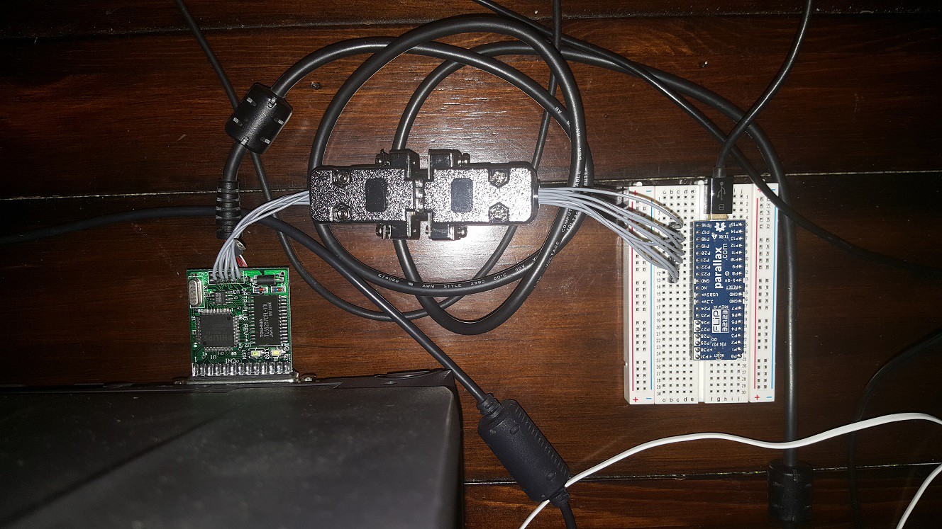
The photo above is a closer look at the actual test setup which is mostly hidden by the laptop in the previous picture. The DCC-link plug is on the left and the excellent Propeller FLiP is on a breadboard on the right. I found two 9-pin Sub-D connectors in my parts bin that I used to make the breadboard and the DCC-Link plug easy to disconnect. Yes, the Sub-D connectors are only 9 pins; the DCC-Link cable has 10 connections but I don't need the +5V output from the recorder.
I hope the long unshielded cables won't be a problem but I don't know yet. If they do, I'll have to replace the cable, possibly make it shorter too. We'll see. For now, I guess I had better get back to writing some software for the Propeller to analyze the serial traffic.
Post Script
As it turned out, the problem with my first DCC-175 was apparently a defect in the heads. With a working PCB2 from one of the DCC-170s it played only analog tapes but not DCC's, and various other PCB2's didn't solve this. I decided to sacrifice my worst DCC-170 to make my old DCC-175 work again. That DCC-170 had mechanical trouble (severe wow and flutter) that made it impossible to play DCC's and made analog cassettes sound horrible, and the DCC-175 had some problems with lifted PCB traces on PCB2 because I had taken it apart so many times. There were other problems like partially melted plastic parts because I had touched them with a soldering iron. There were also missing screws.
After I combined the best of both, I now have two working DCC-175's and two working DCC-170's and one DCC-170 that I might use for parts and repairs in the future. Less than I hoped, but more than I could wish for when I started on this. Oh well, that's what spare recorders are for.
Unfortunately, I had a small soldering mishap: I wanted to replace a blown fuse from the DCC-175 with a different one, and when I desoldered the old fuse, a tiny ball of solder landed between the pins of a tiny transistor, which released its magic smoke when I powered it up (and blew the fuse again). The recorder still works, but when you turn the power off, it goes into perpetual rewind mode. I'll have to look into that some other day.
Discussions
Become a Hackaday.io Member
Create an account to leave a comment. Already have an account? Log In.