 Arnov Sharma


ZK-502MT 2.0 Stereo Bluetooth Amplifier Board
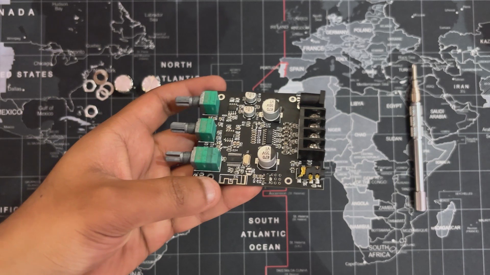
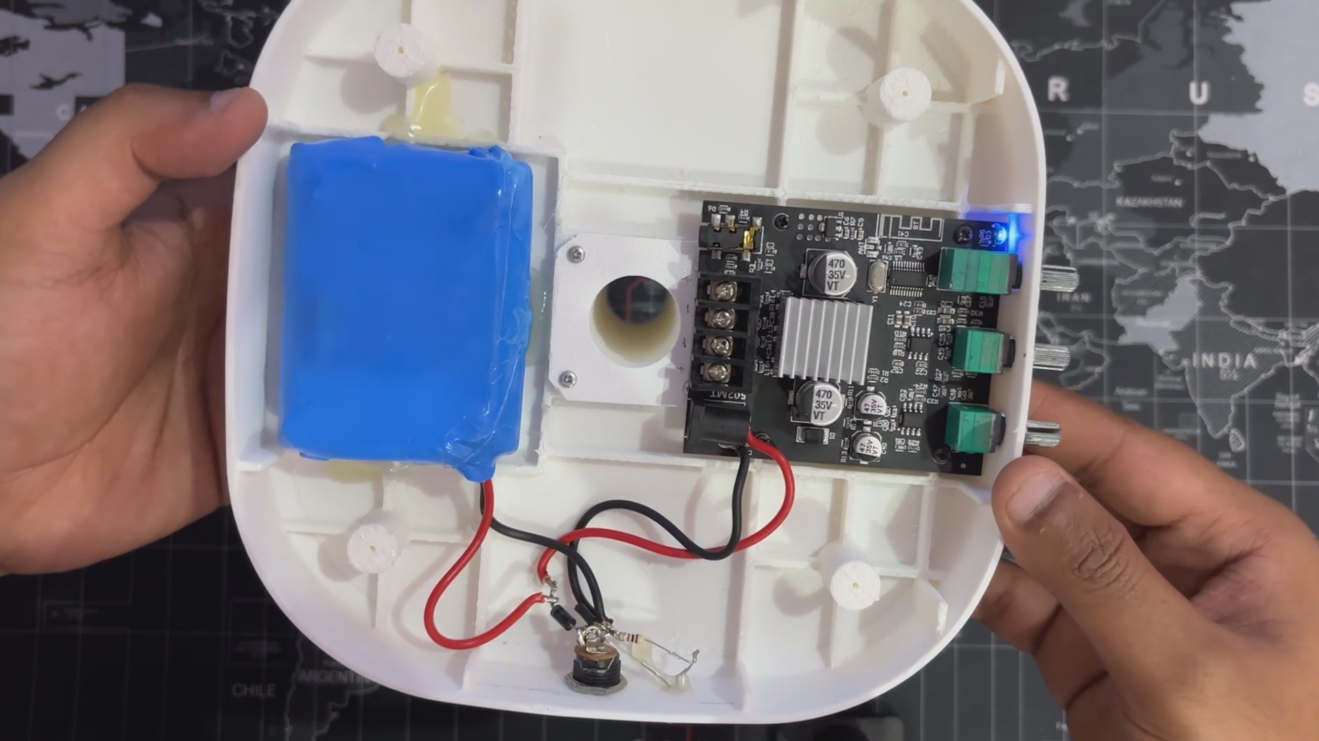
We're using the ZK-502MT Stereo Bluetooth amplifier board that features the CS8663E which is a high-efficiency Class D audio amplifier IC designed for stereo and mono applications. It’s especially popular in DIY audio builds due to its simplicity and performance.
Its standout feature is the ability to deliver 2 × 50 W of clean Class D output, making it ideal for powering medium- to high-wattage speakers with minimal heat and high efficiency.
It supports both Bluetooth and AUX input, giving users flexible connectivity, and includes manual bass and treble adjustment knobs for real-time tone control without external EQ modules.
With a wide operating voltage range (9V–24V) and built-in protection circuits, it’s engineered for reliability and ease of integration into custom enclosures—perfect for makers building portable or embedded audio devices.
PCBWAY GIFTSHOP
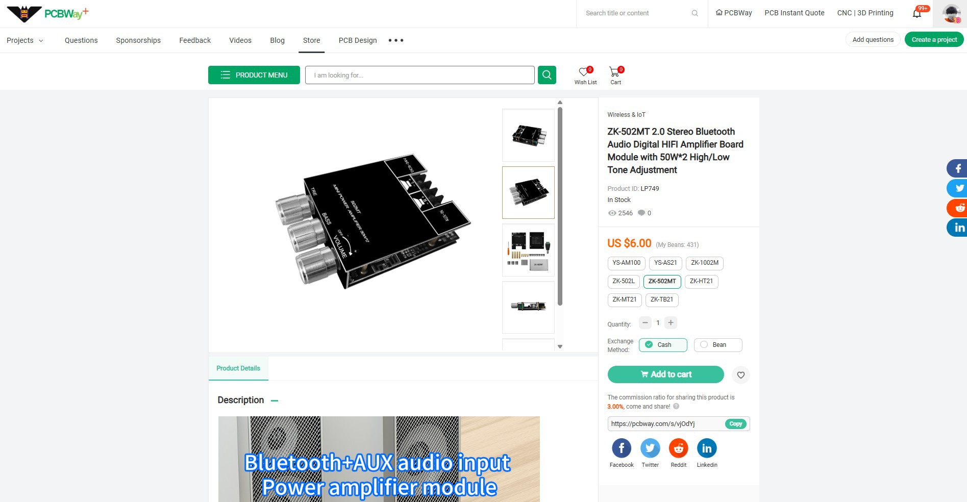
As for sourcing this Audio Module, I got this circuit from PCBWAY's gift shop.
PCBWAY Gift Shop is an online marketplace where you can get a variety of electronics modules and boards for their genuine price, or you could use the PCBWAY currency, which is called beans.
You get beans after ordering something from PCBWAY as reward points, or you can also get them by posting any project in the PCBWAY community.
September Specials from PCBWay!
This month, PCBWay is rolling out two unbeatable limited-time offers perfect for makers and engineers. First up: the iconic Purple Solder Mask, usually priced at $38.43 for 10 pcs of 2-layer 100x100 mm PCBs, is now just $5—a bold color at a bold discount. And for 3D printing enthusiasts, TPU filament starts at $7.96, down from $12.45, with bulk discounts reaching up to 80% off. Whether you're prototyping a new board or printing flexible parts, September is the time to stock up and save. Don’t miss out!
Check PCBWAY out for getting great PCB service from here: https://www.pcbway.com/
3D DESIGN


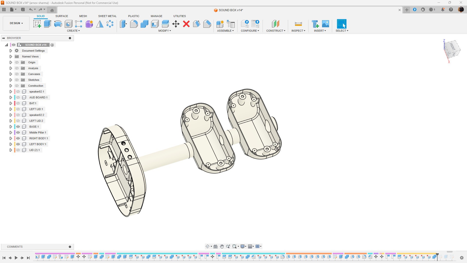
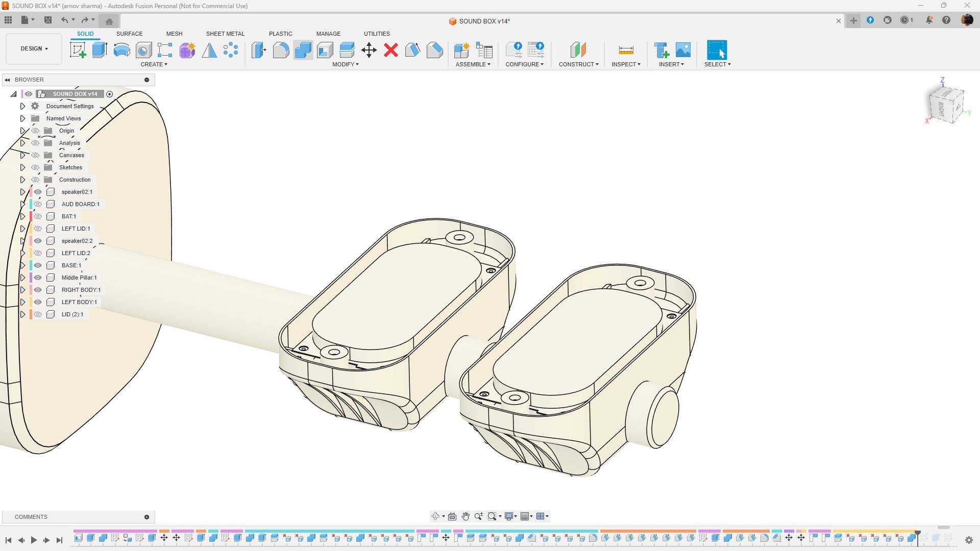
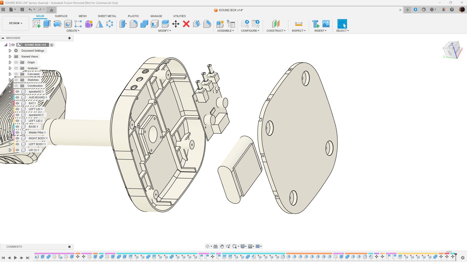
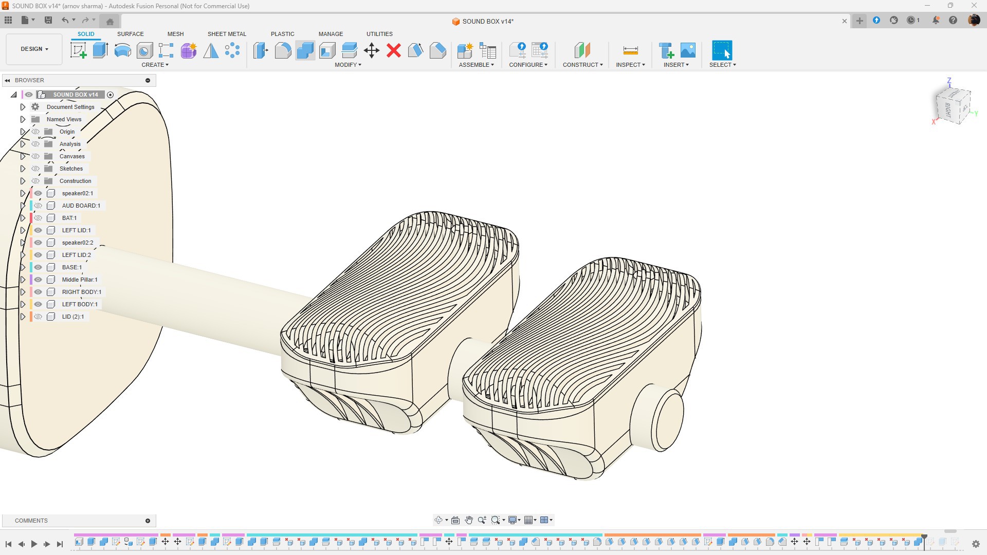
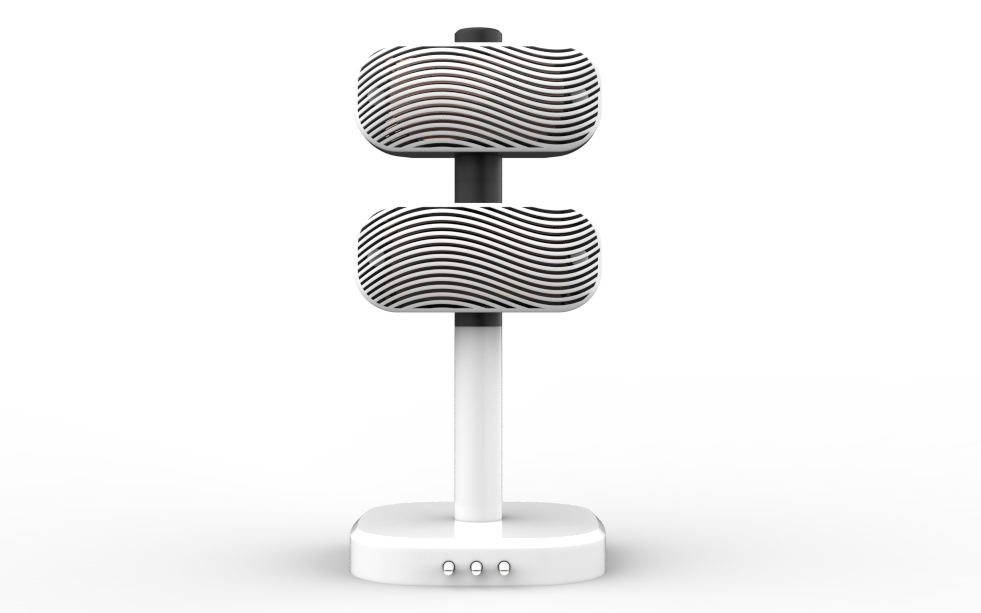
We kicked off this project by rethinking the design from the ground up. The goal was to break away from the conventional boxy speaker format—which dominates most designs and frankly feels uninspired. Instead of sticking to that rigid shape, we wanted to explore something more dynamic and visually engaging.
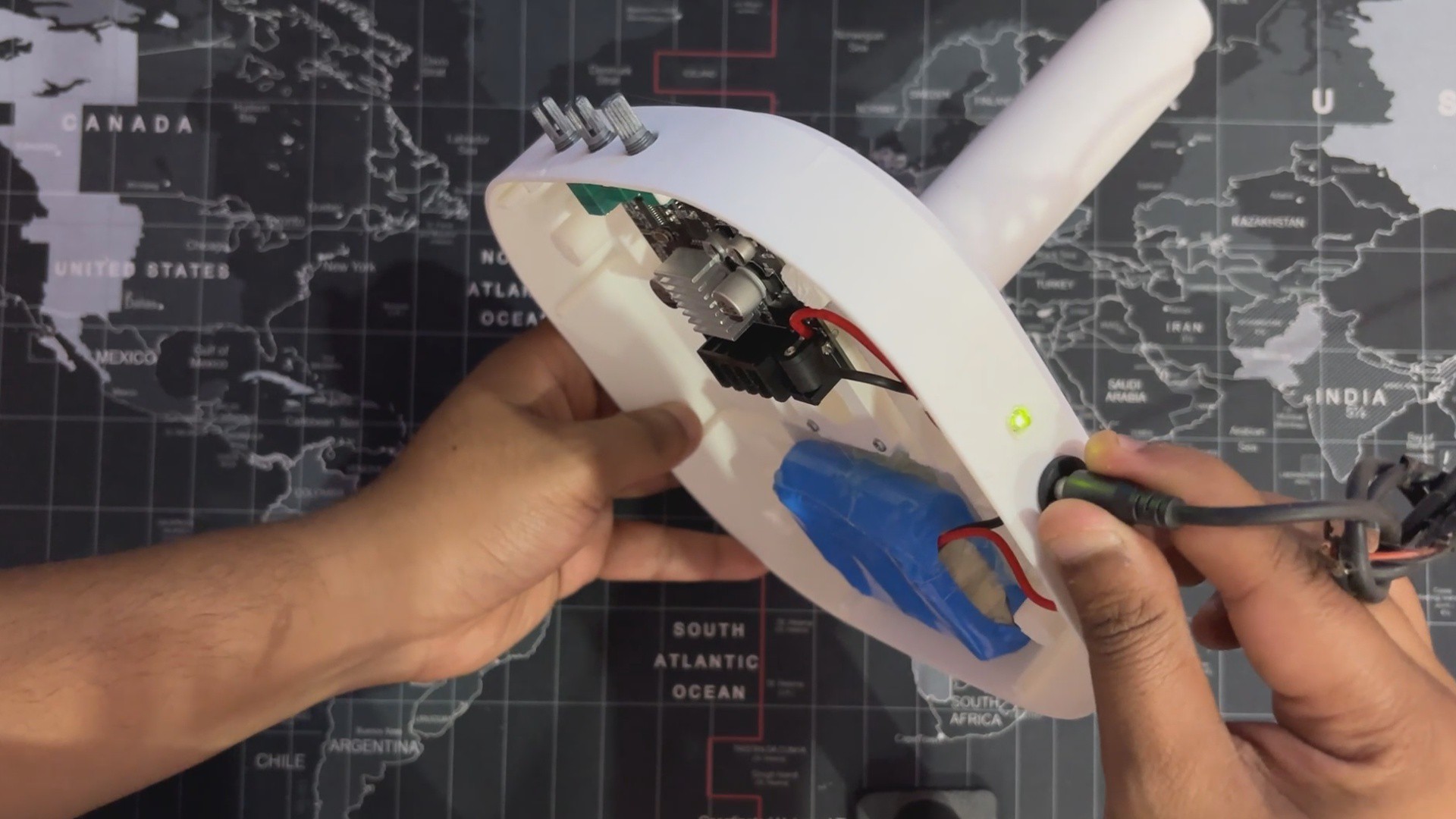
Our design starts with a central base that houses the audio module and battery. From there, the speaker units are mounted externally and connected to the base via a pipe-like structure. This connecting pipe plays a key role: it not only physically links the speaker bodies to the base but also cleverly conceals the wiring.
Each speaker is enclosed in a custom shell, split into two nearly identical halves—Speaker 1 and Speaker 2. Inside each half, we’ve added screw bosses for securing the drivers with M2 screws, along with a dedicated boss for embedding magnets. These magnets allow us to snap on the front mesh cleanly and securely.
To elevate the visual appeal, we designed the front mesh with a flowing, wave-like pattern. This detail gives the speaker a distinct character and helps it stand out from traditional designs.
MODULARITY

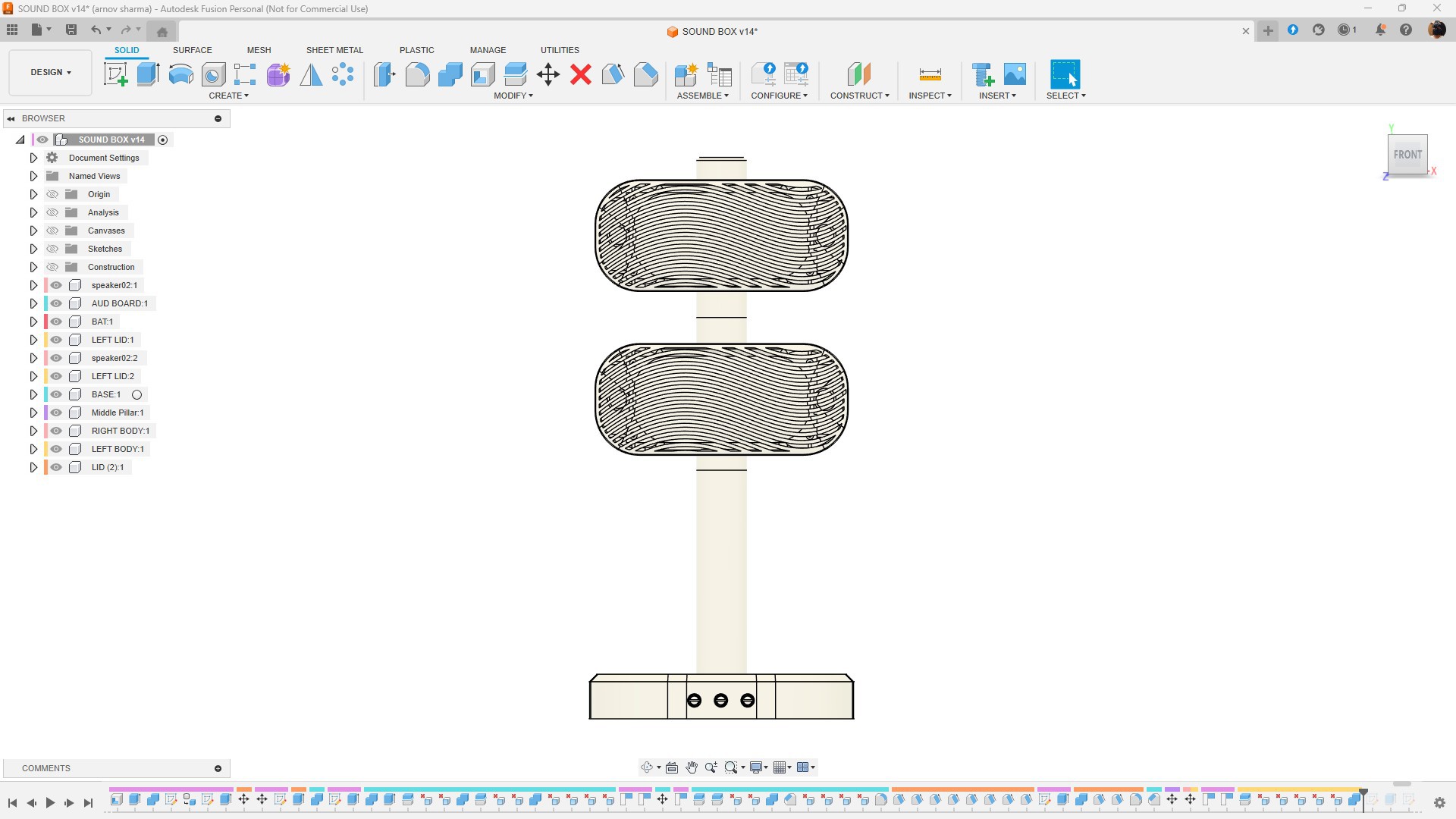
One of the standout features of our build is its modular speaker holder design, which allows us to easily double the number of speakers if needed. The setup includes two speaker holders connected by a pipe-like structure. Speaker 1 nests into Speaker 2 through this connecting pipe, and by repeating the Speaker 2 housing, we can scale the system from a 2-speaker setup to a 4-speaker array.
The beauty of this approach is that Speaker 1 remains unchanged, while Speaker 2’s enclosure can be duplicated as many times as needed to boost sound output. For our current version, we’ve kept it simple with a standard 2-speaker configuration—but the design is ready...
Read more »


 Filip Mulier

 Fabien-Chouteau

 ronald
 Sam Pullman