 Dorijan
- - - Hello, World! - - -
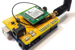
- The module comes nicely packed in a box and in a ESD bag.
- The first thing to consider is that the IO pins are made for 3V3 and do not have clamping diodes. This is one of the reason I opted for Raspberry Pi version since the only 3V3 "Arduino" I own is my own design Arduino pinout compatible AVR board witah ATmega328PB and is barely tested since it was finished only few weeks ago and designed with Atmel Studio in mind not Arduino IDE.
- Most of the documentation and files is on the RF explorer site http://j3.rf-explorer.com/61-rfe/getting-started/179-internet-of-things-products . Among them is the pre-made Raspbian image with everything necessary already installed and setup. User name and password remain default(pi / raspberry)
- in the root directory there is a readme file with basic instructions where to find the 2 pre-made examples
- 1st example constantly searches for the peaks and the 2nd one scans the the RF spectrum
- - - For now module works and is operational - - -
- - - What does this pin do? - - -
- After sifting through arduino code I noticed that it only uses 2 extra pins besides serial port
- Reset and GPIO2 pin, reset is self explanatory, and GPIO2 is commented as ( LOW -> Device mode to 2400bps )
- Potential problem could arise since even though GPIO2 is used as output it is nowhere defined as output. Which on AVR MCUs means that is in the default( INPUT ) mode. But it is possible the module still works since pull-down on the module is 2k2 and setting it to HIGH sets the internal Pull-UP resistor in AVR. (will notify the team to check that)
- The following is the list of the GPIO pins:
RFE_RESET A4 // pinMode(_RFE_RESET,OUTPUT); _RFE_GPIO2 A0 // output - although it is nowhere specified as such //Possibly ther is a pull down on the circuit so it works despite that mistake #define _RFE_BUZZER A5 // not connected to module - assumed output(buzzer) //Folowing are not used in this example - therefore assumed input #define _RFE_GPIO0 13 // could be TXA of software serial #define _RFE_GPIO1 11 // could be RXA of software serial #define _RFE_GPIO4 A1 #define _RFE_GPIO5 A2 #define _RFE_GPIO6 12 #define _RFE_GPIO7 10 #define _RFE_RFGPIO0 6 #define _RFE_RFGPIO1 4 #define _RFE_RFGPIO2 5 //TXA and RXA are meant TX / RX for arduino - And since I am using board with ATmega328PB - one small modification is also needed
// in file RFExplorer_3GP_IoT.h #if defined(_SAM3XA_) && defined(__AVR_ATmega328PB__) #error REVIEW COMPILATION DEFINED BOARD #endif #if !defined(_SAM3XA_) && !defined(__AVR_ATmega328PB__) #error REVIEW COMPILATION DEFINED BOARD #endif - Code compiles in Arduino IDE so I installed the shield
- Quickly it started to pull 100mA of current - this is OK initially when device is initalasing...
- ... but. Serial is acting strange...
- Basically the code sets the module with HWserial, receives the configuration from module with2400 baud, and then also data from module with HWserial. Plot is transmitted on software serial pin13( PB5 )
- I am using a second USB uart adapter for receiving this plot data
- I have modified the code to add headers to plot data
- It requires constant switching of uart0(so arduino can talk to module) and uart3(so computer can program arduino)
- There is a option to use the second UART on ATmega328PB and modify connections
- - - By this point I am able to receive "some" plot and have general idea how to proceed - - -
- - - Making it work with arduino and arduino plotter - - -
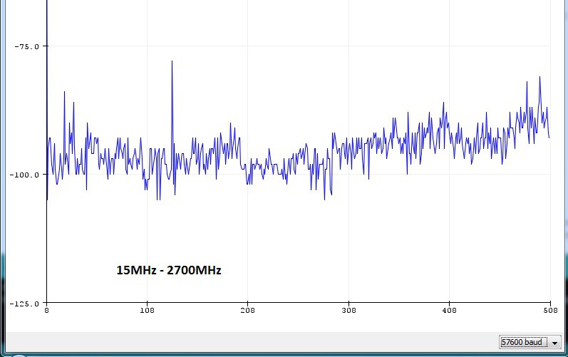
- My goal for now is streaming full spectrum(15MHZ to 2.7GHz) scans constantly to arduino plotter with minimal 1Mhz or better RBW resolution.
- First to start with a nice read also known as RTFM on the internet: https://github.com/RFExplorer/RFExplorer-IoT-for-Arduino/wiki/Library-reference - BTW no PDF so printing the manual gives mixed results.
- I have managed to write to general serial plotter code where you insert start frequency, stop frequency and required precision.
#define _START_FREQ_KHZ 15000 //kHz #define _STOP_FREQ_KHZ 2700000 //kHz #define _RBW_KHZ 5250 //kHz - The problem is, that I am unable to put more than 500 points on the arduino plotter. So the above settings give us full range(15-2700MHz) in the plot
![]()
- And the following is the WiFi plot 2400-2500MHz
![]()
- Now I am able to get a full scale plot.
- Next thing on the list will be how to display frequencies on the graph, adding option for logarithmic plot, better control filter bandwidth, figure out how to switch between ranges (attenuator, 0dB, LNA) and speeding up the refresh rate of measurements
- Although code is very messy and I have some major issues with variable definitions. Let say it is at least barely useful.

- - - So now I am at the point I can at least partially use the module as I want to - - -

 nootropic design
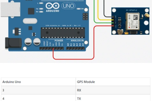
 shashikanth
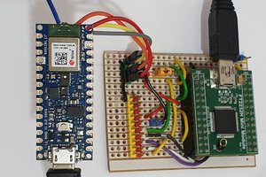
 Tim
Tim
Maybe this project can help to inspire the fully DIY version: https://www.changpuak.ch/electronics/Arduino-Project-SPECTRE.php
In addition RF Explorer released a RFETouch application for Raspberry Pi which converts the RF Explorer 3G+ IoT in a DIY spectrum analyzer with no need for further code. It can be used with touchscreen or normal screen.
More details at www.rf-explorer.com/touch