 Neil K. Sheridan
Here we show how to allow the dayPi and nightPi to share the PIR and light-sensor!
PARTS REQUIRED:
- half-length breadboard
- PIR
- light-sensor with digital output
- numerous jumper cables!
- dayPi
- nightPi
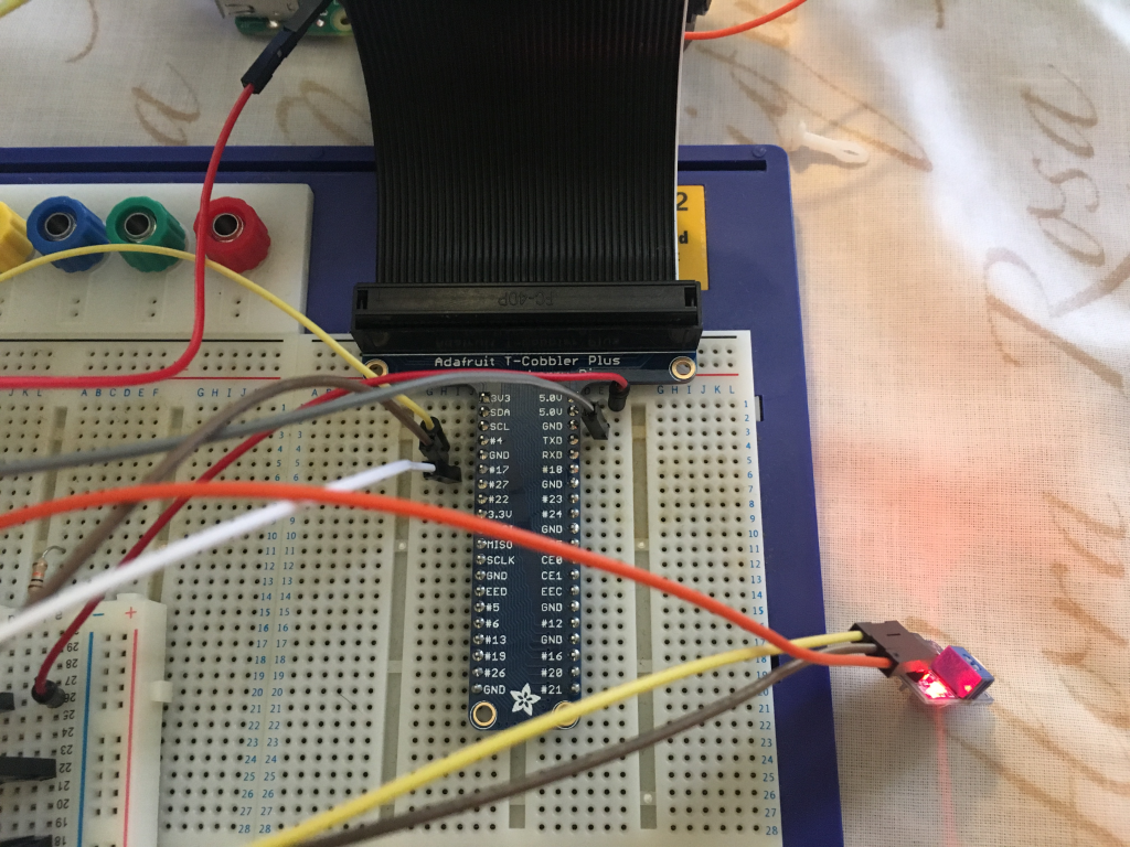
- * I used the Adafruit cobbler for testing
Let's get started!
1. Let's do the light-sensor first. This has a 5v input, a GND, and digital output (giving HIGH or LOW depending on lighting conditions). We need to connect all of these to independent terminal strips on the breadboard. So for example:
5v goes to terminal strip 1. So we connect a jumper wire from this terminal strip to the 5v output on nightPi
GND goes to terminal strip 2. So we connect two other jumper wires to this terminal strip. One will go to GND on nightPi and one will go to GND on dayPi
Digital output goes to terminal strip 3. So we connect two other jumper wires to this terminal strip. One will go to GPIO 11 on nightPi, and one will go to GPIO 11 on dayPi. [note this is BOARD numbering for the GPIOs]
Let's see what this looks like with a photo! This includes the wiring for the PIR, which is the same kind of thing but to GPIO 7 on each Pi for the digital output!
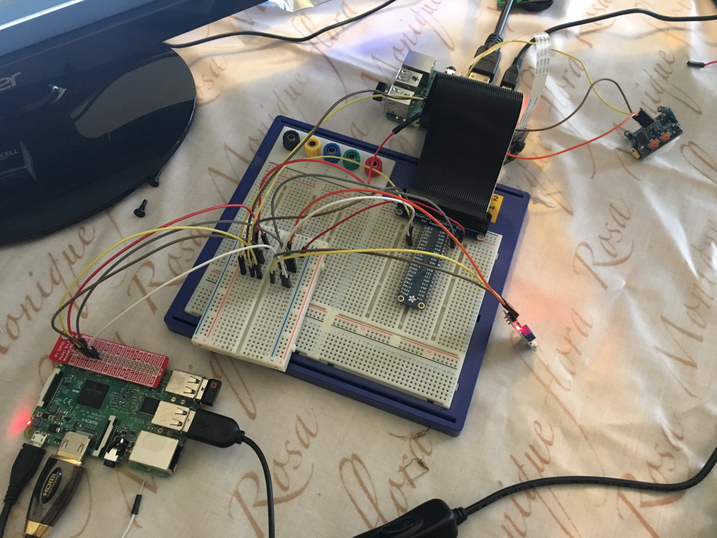
2. Now let's to it for the PIR. In the photo you can see the light-sensor is wired to the terminal strips on right of divider, and the PIR is wired to terminal strips on the left of the divider (the middle groove of the breadboard).
5v goes to terminal strip 1. So we connect a jumper wire from this terminal strip to the 5v output on dayPi
GND goes to terminal strip 2. So we connect two other jumper wires to this terminal strip. One will go to GND on nightPi and one will go to GND on dayPi
Digital output goes to terminal strip 3. So we connect two other jumper wires to this terminal strip. One will go to GPIO 7 on nightPi, and one will go to GPIO 7 on dayPi. [note this is BOARD numbering for the GPIOs]
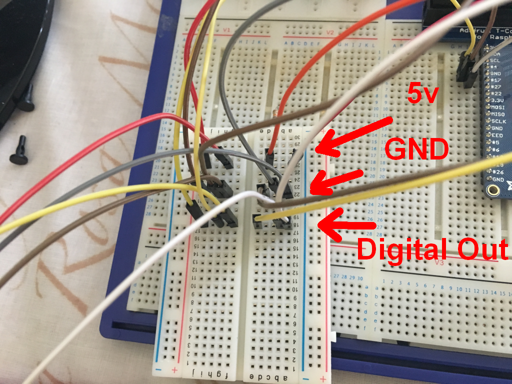
If you zoom into the photo, you should be able to follow the paths of the wires!
Here's a close-up of the breadboard. You can see how 5v input to the light-sensor and PIR is sent to the first terminal strip, and then it meets the 5v output from the Pi there. Thus we supply power to the light-sensor and PIR. And GND from the light-sensor and PIR goes to the next terminal strip, and from there is sent to GND on both dayPi and nightPi. And digital outputs from light-sensor and PIR go to the next terminal strip down, and they meet wires which take them to the GPIO PINs on dayPi and nightPi.
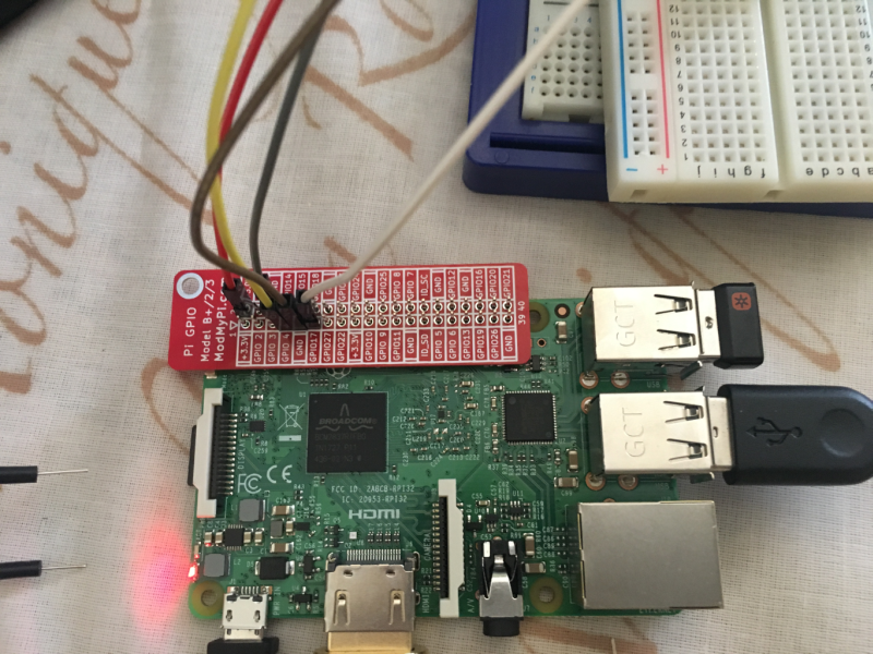
And in the below photos you can see the wires connecting with the dayPi and nightPi:
3. Great! We are all ready to share the PIR and light-sensor now!
Discussions
Become a Hackaday.io Member
Create an account to leave a comment. Already have an account? Log In.