 Neil K. Sheridan
So for this we need wires, connectors for the battery, a lead acid battery, a charge controller, and a solar panel!
WHICH BATTERY AND SOLAR PANEL SHOULD YOU USE?
From an earlier log, I investigated how to calculate the type of solar panel and battery required. This is dependent on local conditions.
SOLAR PANEL
What is the output power of the solar panel we need?
First we need to determine the total energy usage of the device in 24hr period (Watts). We can put this into the following equation as E. Whilst the output power of solar panel is P(solar). Let's supply the total time solar panel is in direct sun as 10hrs
P(solar) = E / (10*60*60)
BATTERY
Now how long do we need the battery to be able to deliver energy without solar charging? Obviously this is all kinda rough. We can go ahead and use a solar insulation map to determine more exact number of hours solar panel is in direct sun at a given time in year. So let's say anyway, we want the battery to deliver 48hrs of energy without any charging:
C(battery) = E / V*60*60
Where V = voltage we need, and C(battery) = storage capacity in Ah, and E = energy usage of device.
COMPONENTS USED FOR THIS EXAMPLE BUILD
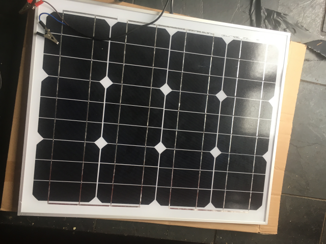
- 30W Solar Panel
- 12V 17.8Ah Lead Acid Battery
- 18 AWG Gauge Electrical Wire (black and red)
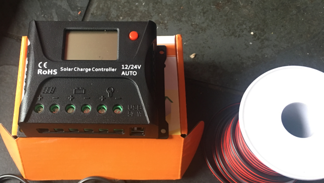
- HQST 10 Amp 10A PWM Smart Solar Charge Controller 12V/24V Solar Panel Battery Regulator with LCD Display USB Port (£16)
- Multimeter
- Wire cutters
- Wires with crocodile clips and bare ends
- Screwdrivers
BUILD INSTRUCTIONS
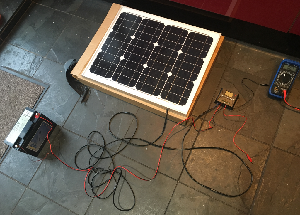
1. Assemble the components
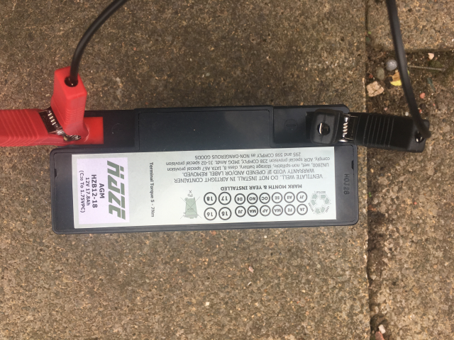
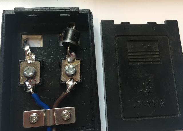
* the big clips on the battery are for charging from AC. You'll need to charge your battery in this way before you deploy it.
2.
Cut the wires. The charge controller takes bare wire ends, so you need to strip the wires. First off I cut two wires (red and black) to an appropriate length for connecting the battery to the charge controller. I stripped these on both ends. Then I cut off the crocodile clips from the wires that are attached to the solar panel, and stripped them, ready to attach to the charge controller. Make sure you are aware which is -ve and +ve coming from the solar panel! In my case it was brown +ve and blue for -ve. You can see the layout in the following diagram:
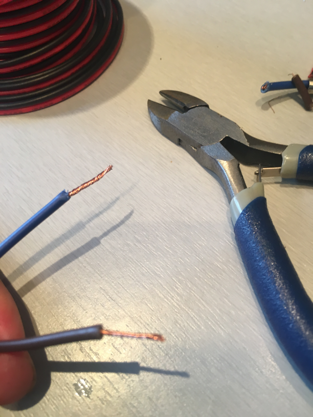
Above you can see the outputs from the back of the solar panel. Remember to verify which is +ve and which is -ve!
3.
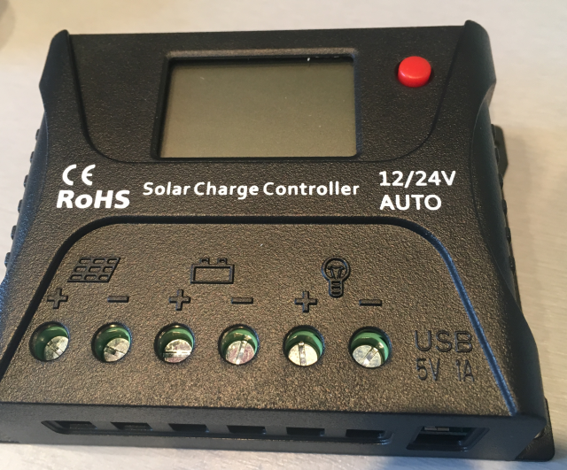
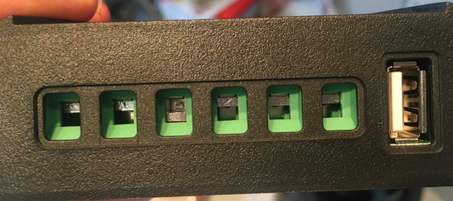
Now all the wires are ready, we can connect the other components of the solar charging circuit to the charge controller. The inputs are marked. On mine, I have solar panel input, battery connection, 12v output, and a USB 5v output. Unscrew the top screws so you can push the wires into the slots, then screw them up again!
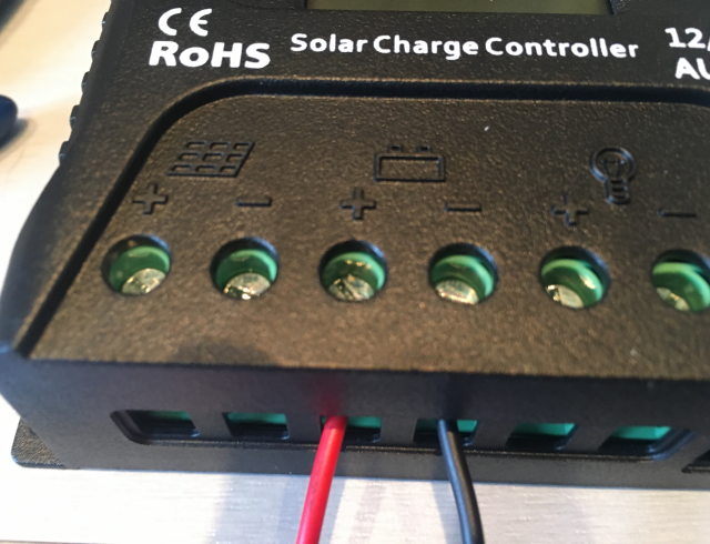
Above you can see the +ve and -ve (red and black) wires for the battery connected to the charge controller. In the photo below you can see everything is connected! We are all ready to go! I've uploaded it sized so you can zoom in!
4.
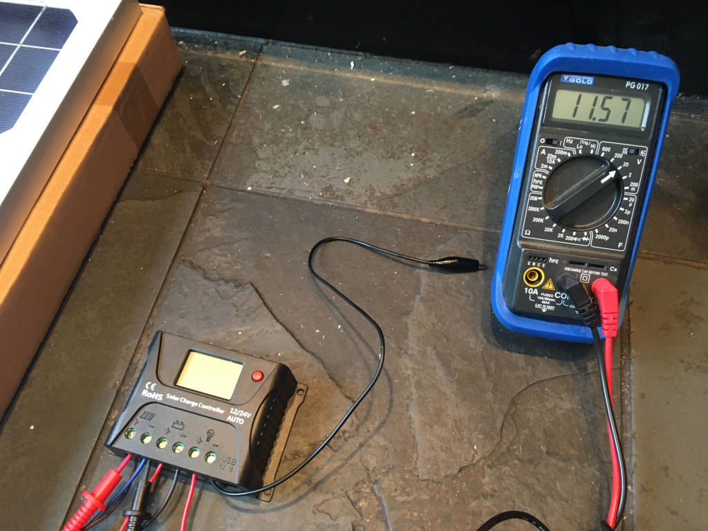
Now it's a good idea to do some checking using the multimeter. First I checked the voltage coming out of the solar panel. This was just by connecting the multimeter to intercept the inputs from the solar panel to the charge controller. I got around 12v as expected.
Next, I wanted to see the current coming out of the solar panel. This is quite fun, because you can see it change according to how much light is hitting the solar panel! You can see this in the video below when I turn the indoor light on and off (it was raining so I couldn't do it outside):
So everything seems ok with the solar panel! Let's see what's going on with the charge controller. I won't go into details for this specific controller, as it would be unlikely you will use the same. In the video below we can see what the LCD display gives us when the entire solar charging circuit is up and running. Note that E0 = error code zero (i.e. no errors). It gives voltage, battery temperature, and % of charge.
5.
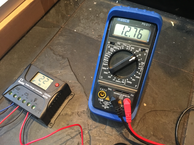
Ok, so let's check the outputs from the charge controller. With this model we have a 12v and a 5v USB. I checked the 12v output by connecting wires with bare ends on one end to the charge controller, and crocodile clips on the other, to my multimeter. You could test the USB C output by checking the power pins (the pin outs are listed here https://en.wikipedia.org/wiki/USB-C#Connector_pinouts) but honestly it would be rather excessive, and time-consuming if you don't have a USB cable tester. But hey, if there's time and you don't want to risk damaging a raspberry pi then you could do it! Anyway, we got 12.76v output from that 12v output on the charge controller.
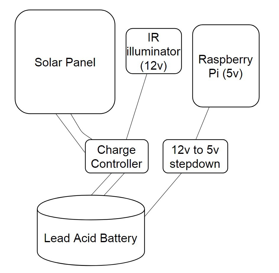
In the elephantAI system, we'd use the 12v to supply power for the IR illumination on the detection devices, and the audio amplifier on the deter devices. This particular model has a USB C connector outputting 5v. So, that can power the Raspberry Pi components. But in other models, you may only get a 12v output, so will have to step this down to 5v to power the Raspberry Pi components of the ElephantAI.
The easiest way to do this is to google "DC-DC Converter Step Down Module 12V to 5V Micro USB Output". You can pick these up for £6-£12 on amazon or ebay. Failing that you can look for a a converter "car power supply 12v to 5v". But these only have +ve and -ve outputs. So you will have to hook these wires up to a micro USB connector. There's a tutorial for doing that here: https://geekhack.org/index.php?topic=44924.0
You can also build your own circuit, perhaps using an IC 7805 (Voltage Regulator IC), heatsink, etc. I'll try to find time to show how to build this.
So, that's it! The solar charging circuit is all ready to go once it has a waterproof enclosure for the battery, and a mount for the solar panel!
CONCLUSION
You can use the batteries, charge controllers, and solar panels that are available easily and cheaply to you for building the solar charging circuit. As mentioned at the start, you can decide on the battery capacity and the solar panel type depending on local conditions. You certainly don't have to use the same components as I have done! You can build your own charge controller of course, it would be cheaper, I'll try to outline a build if I have time!
Discussions
Become a Hackaday.io Member
Create an account to leave a comment. Already have an account? Log In.