 alexw
alexwThe glider has 2 physical sections internally, the first is the buoyancy engine section and the second is the control boards and the pitch mechanism. The current design (below) uses pogo pins and a pair of boards to electrically connect the two sections, however this has two main downsides.
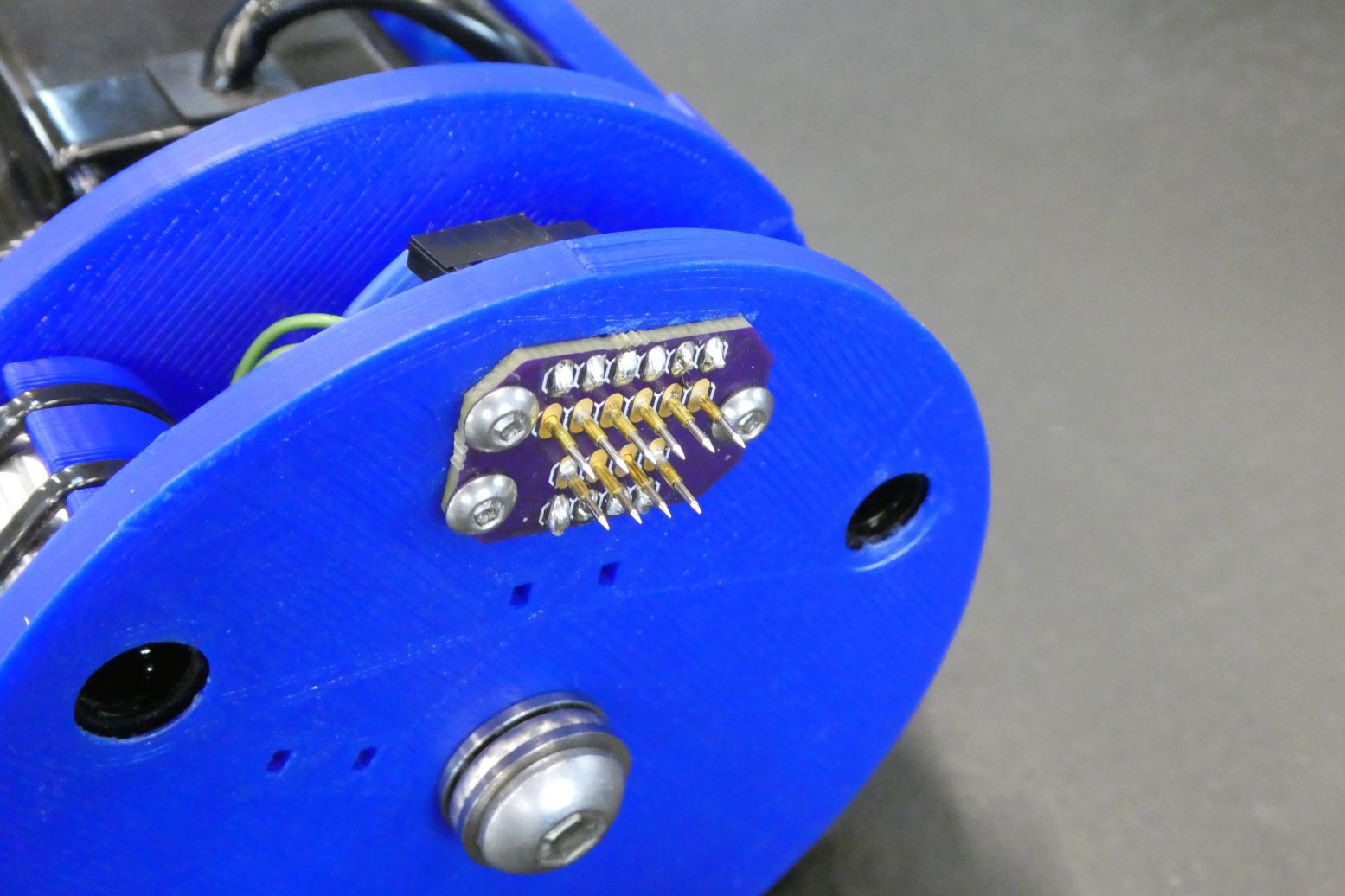
The first problem with the pogo pins is that they use a spring mechanism in order to ensure a reliable connection, this causes the two sections of the glider to be pushed apart when the glider is assembled, which reduces the reliability of the connection. The other issue with this connection type is that the travel of the pogo connectors is only a few mm, which means that the rest of the glider must be aligned to within a couple of mm - the current solution to this is the sliding mounting bracket of the pogo connector PCB.
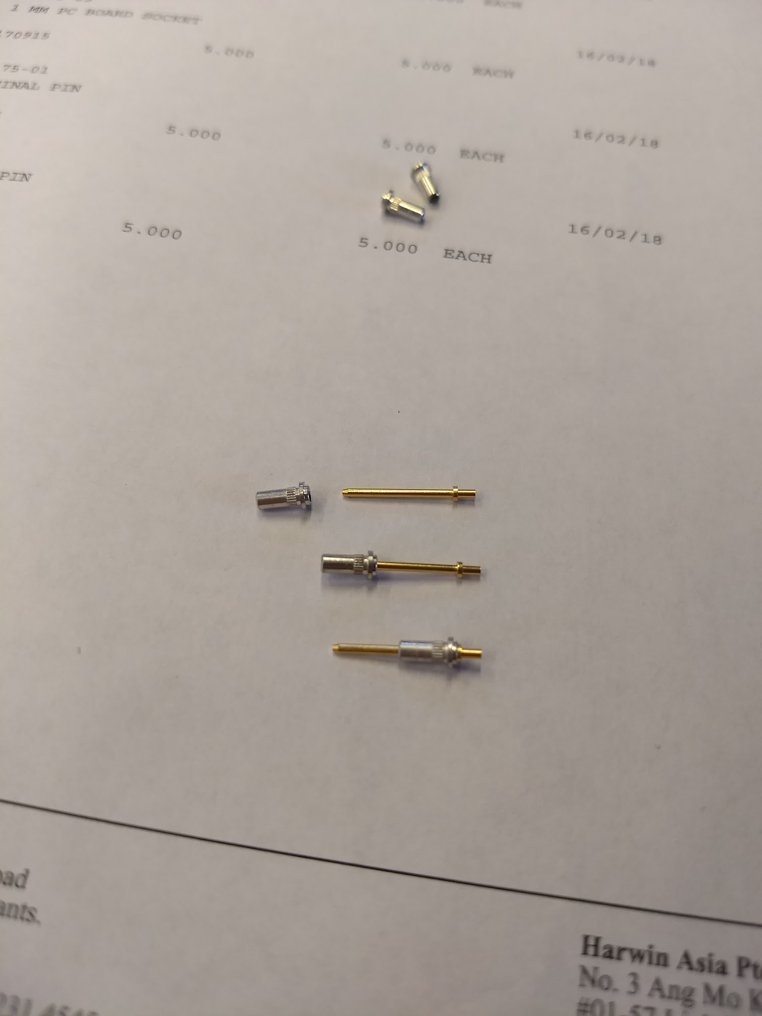
With this in mind, the ideal connection would be one that does not have a spring contact and has ~10mm of travel. After having a look I was able to find the PCB contacts from Harwin that do exactly that, namely the H3169 and H2170 connectors.
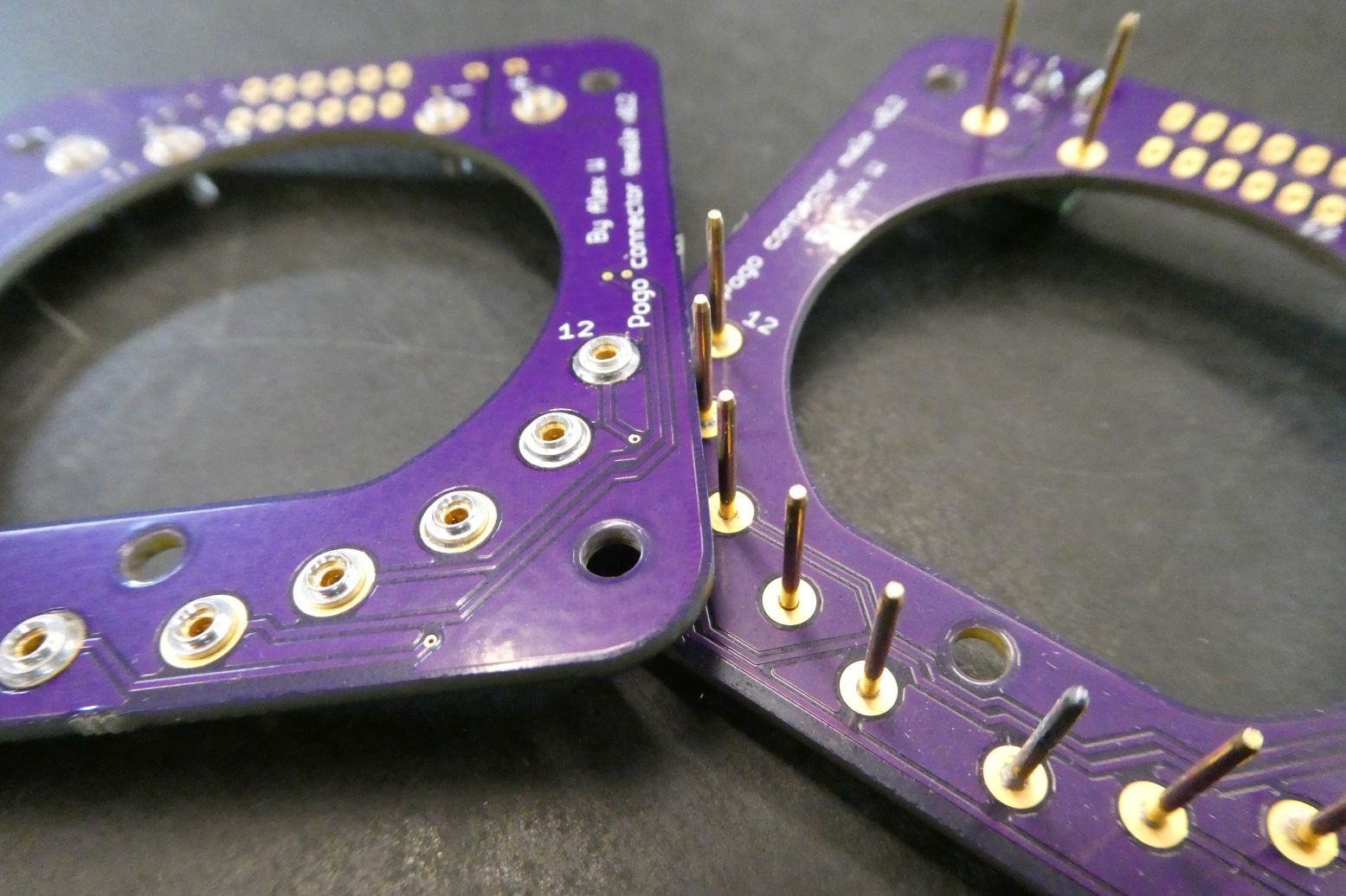
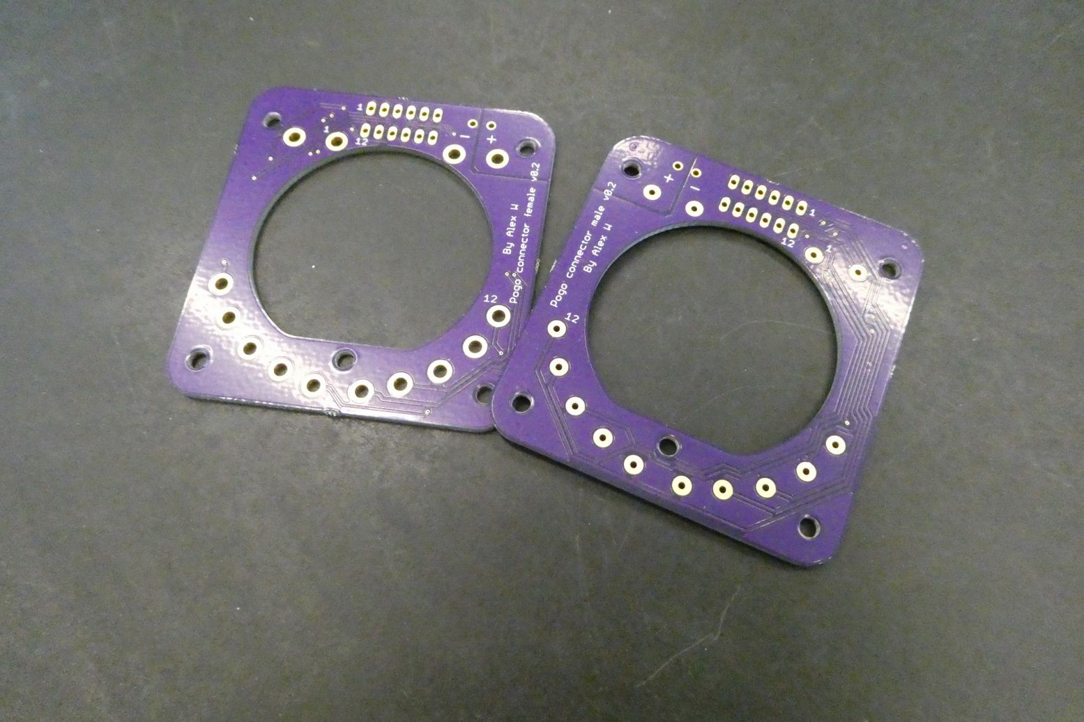
I ordered some sample connectors and they came through and were a perfect match for what I wanted, so I went ahead and purchased ~20 more connectors and designed some boards in Eagle for the two sides of the connector. Below is an image showing that the connectors in varying positions, all with solid electrical connections.
I designed some updated boards for the ordered the PCBs through OSHpark and a massive shoutout to Drew (@pdp7) for providing great customer service and making sure I got my boards within a week. Below are some images of the boards and what they look like with the PCB connectors attached.
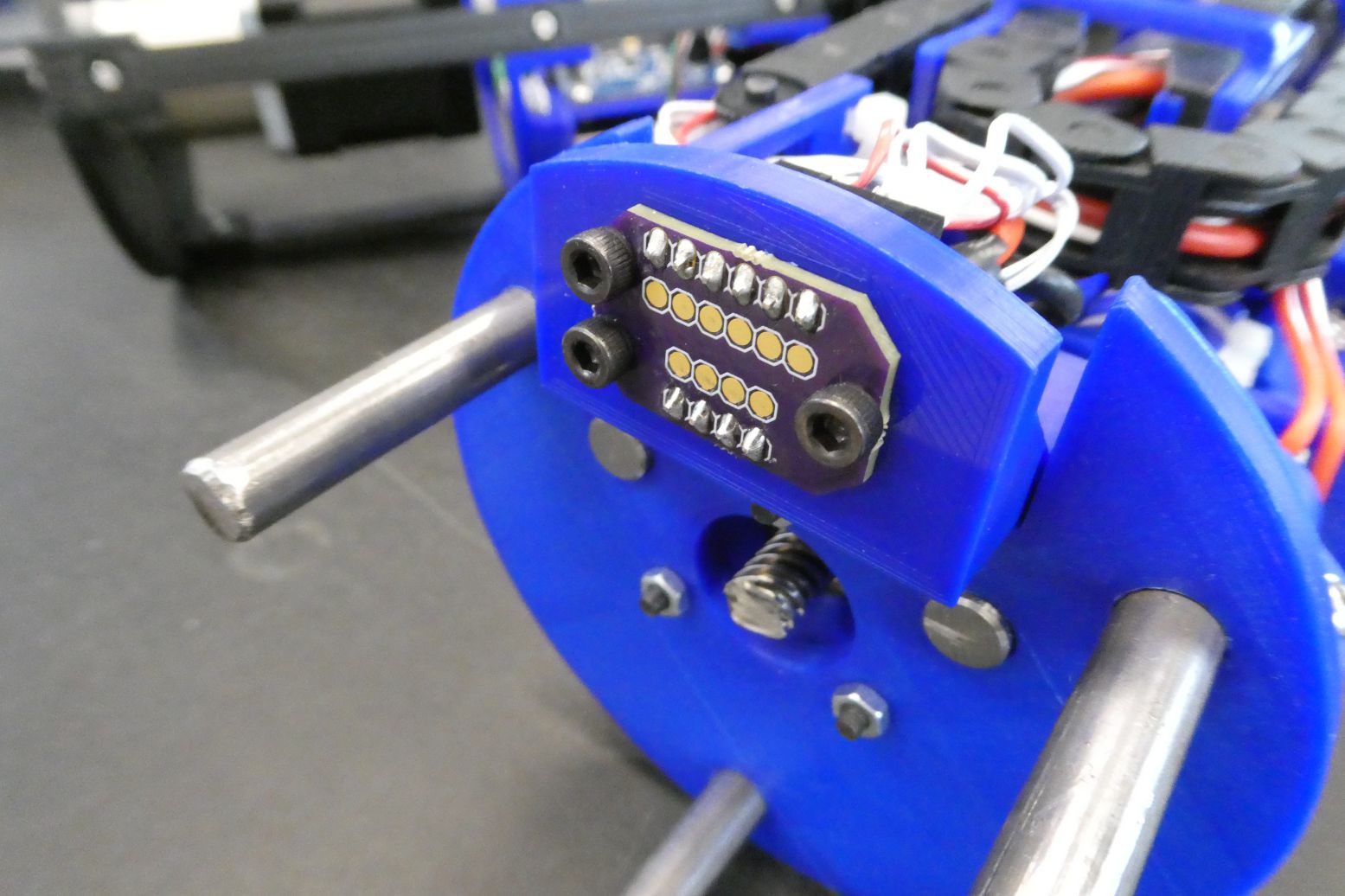
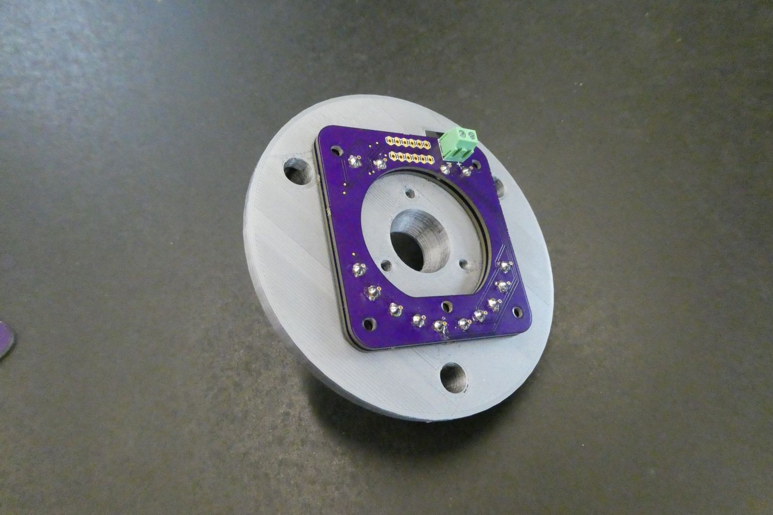
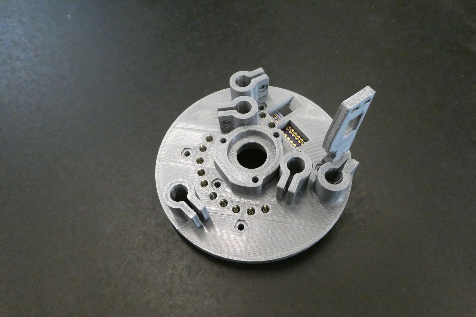
This new configuration also more equally distributes the force of the contacts through the plate, as opposed to on the small section at the top. I designed and printed an updated PCB mounting bracket and you can see how the board fits in-between the alignment rods:
Although using Onshape was an interesting experience, I am now transitioning to Solidworks for the design of the glider, but understanding that not everyone has access to Solidworks, I will still be providing the STL files so anyone can download and print the parts. The PCB files are also in the Dropbox development folder.
Discussions
Become a Hackaday.io Member
Create an account to leave a comment. Already have an account? Log In.