 alexw
alexwSeveral modifications to the control board PCB have been made.
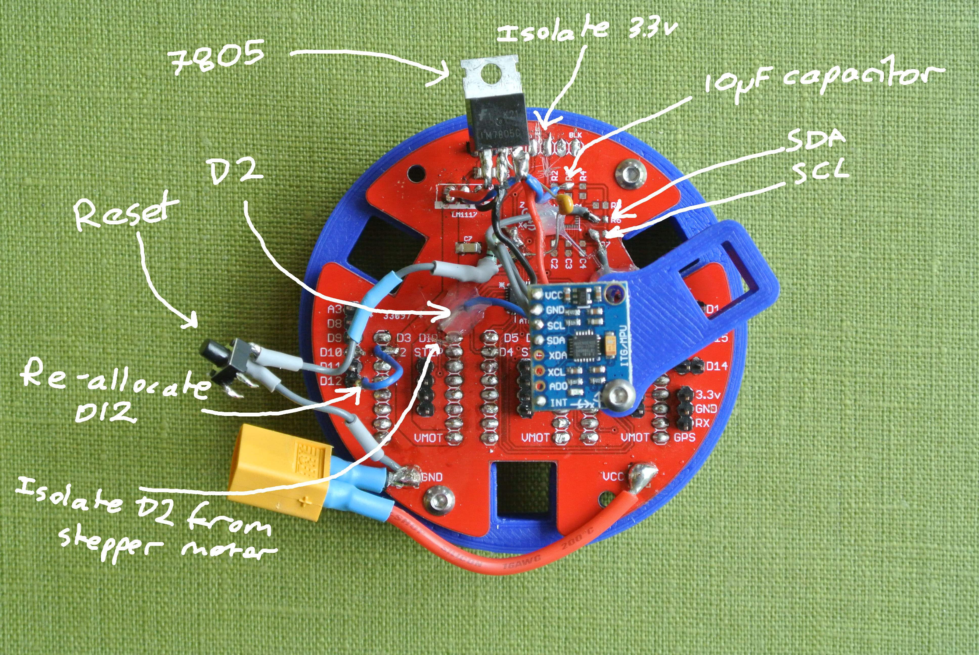 As the IMU that I was going to use (LSM9DS1) is out of stock until November, I had to modify the board to use an alternative IMU (MPU6050), which does not have a magnetometer. I used the SDA and SCL pads from the board to hookup the MPU6050. I had also set digital pin 2 on the atmega328p to control a stepper motor, however the MPU6050 requires the digital pin 2 specifically, so you can scrape away at the PCB to obtain the D2’s signal track, making sure to isolate the D2 signal from the stepper motor. You have to re-allocate D12 (or any other spare pin apart from D10 - used during program upload so can cause erratic behaviour) to the “Step” pin of the left hand stepper motor driver.
The 3.3v regulator was swapped out for the 7805 5v regulator, as the MPU6050 requires a 5v supply. The pinout of the 7805 is different to the original regulator, so be careful when swapping the regulators. The 3.3v from the FTDI cable will also have to be isolated, meaning you cannot power the Atmega328p by only the FTDI cable, you also require external/battery power. I will add an automatic power supply switching circuit for the board by the next board revision.
To enable auto-reset when uploading, a 10uF ceramic capacitor was linked between DTR/RTS pin of the FTDI cable/adapter.
Although not as necessary, I also added a reset button.
I hope to produce another revision of the board with these alterations soon.
Discussions
Become a Hackaday.io Member
Create an account to leave a comment. Already have an account? Log In.