 Frank Buss
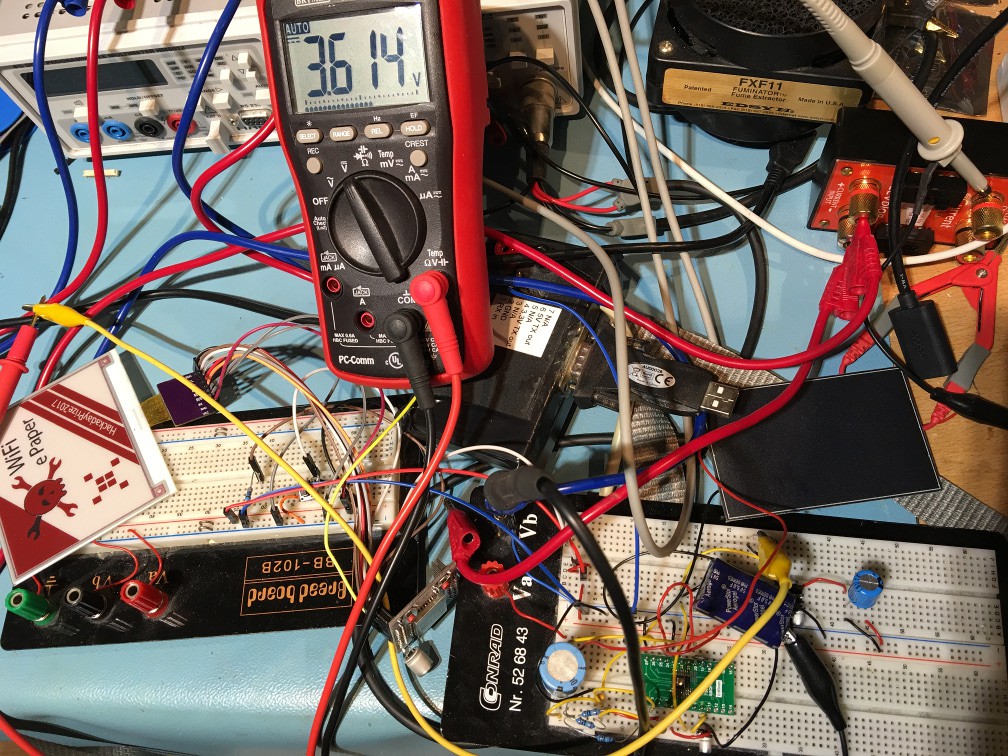
So I bought this shiny LTC3106 power supply IC (costs EUR6.69 at Digikey) and it looks like it has all I need: peak current 650 mA, more than enough for my ESP32, and goodies like Maximum Power Point Control (MPPC) to get the most out of my solar cell. I soldered the IC on a breakout board, this is the final test setup:
But it didn't work. The ESP32 module started but restarted all the time shortly after starting. There were many problems. First I used the solar cell at the Vin pin, as an example in the datasheet says, and a 15 F super cap for Vstore. But in the fine print of the datasheet you can see that the peak current for Vstore is 200 mA, so should be no problem, right? But the valley current limit is only 70 mA for Vstore. It is 400 mA for Vin, but no way I can get this from the solar cell and I can't add the super cap to the Vin input, because then the MPPC wouldn't work.
And there was another problem: Even if I could have managed somehow to get the full current from the super cap, it has an ESR of 30 ohm, so e.g. at 3 V the max possible current would have been 100 mA.
This was a fail, I guess I can't use the LTC3106. The only nice thing about it was the MPPC function, which worked as expected. I connected 1.5 meg ohm to GND from the MPP pin and the MPP voltage was about 2.5 V, the best voltage for my solar cell as you can see in my previous log, and it could charge the capacitor at Vstore to 5 V.
Next I measured the current of the ESP32 while downloading an image and showing it on the e-paper, because I was suspicious why it resetted. The datasheet says 160 - 260 mA when sending with high data rate and max output power, and for receiving only 80 - 90 mA. But looks what I measured:

I used the μCurrent, 1 mV is 1 mA. As you can see, there are spikes of more than half an amp! I guess the datasheet averaged the current consumption, or maybe I did something wrong when measuring it? But no way that I can do this with the LTC3106 or the super cap with the high ESR.
But the solar cell charging part worked, so I changed the circuit: Now the LTC3106 charges only a different super cap, 5 F and 130 mOhm ESR (this one), which now is connected to Vout and I wired the programming pins of the LTC3106 to charge it to up to 5 V. For testing I added a linear regulator from this output (an MCP1703), to create the 3.3 V for the ESP32. Now it was possible to charge the new super cap and the ESP32 could load a new image and then go to sleep again. This is the charging curve with the solar cell and about 300 lux:
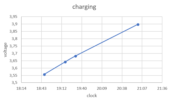
As you can see, it charged the 5 F capacitor with more than 0.3 V in about 2 hours. When I clicked the reset button on the ESP32 to wake it up from sleep and load a new image, the voltage dropped to 3.58 V. So with this setup it is possible to update the display once every 2 hours.
But this wan't the last problem: it didn't work from 0 V. When I discharge the capacitor and it starts charging it, the ESP32 starts drawing more current then the charging current at about 2.1 V and the voltage stays there. But the ESP32 module doesn't start at this voltage, it draws only current. When I hold down the reset button, the charging continues, so looks like this is a problem of the ESP32: it doesn't really work with slow rising supply voltages.
Next I'll try to build my own voltage regulator circuit, using a low power PIC microcontroller to do all the controlling in software, and external FET switches and inductors. The reason for this is because the LTC3106 is too expensive, and it doesn't even fully work as I need it. And then I would need another expensive switching regulator to create the 3.3 V from the 5 V (the linear regulator I used now is just for testing, it wastes half of the energy). I stored the solar cell energy in a 5 V capacitor, because then the stored energy is higher and it needs longer to drop below what the next stage gets needs for minimum voltage, but this might change when I build my own regulator, because there are more good 2.7 V rated super capacitors than 5 V. With the PIC I can also measure all voltages and control exactly when to release the reset line of the ESP32 etc.
Conclusion: my estimation for the number of updates (one per hour) with the solar cell from my last log was a bit optimistic, but I'm sure now that it is possible to do at least a few updates per day, even when the light is not perfect.
Discussions
Become a Hackaday.io Member
Create an account to leave a comment. Already have an account? Log In.
The 4.2" Spectra display you used in your last log needed 10 seconds for a single update. Wouldn't you be able to do roughly 10 times more updates with a standard black and white display with only 1 sec update time? I think that the red in the Spectra sure looks nice but I'm not sure if it's worth the power in your budget.
Are you sure? yes | no
You are right, maybe I allow to use only black/white and no red on the display, because I think if you don't need red, it can be updated faster.
Are you sure? yes | no
Definitely. The red particles need another positive source voltage to be driven than the black ones. The update would cut the whole part using and generating that voltage.
Are you sure? yes | no