 Frank Buss
The new microcontroller on the breakout board is working, this is the test setup:
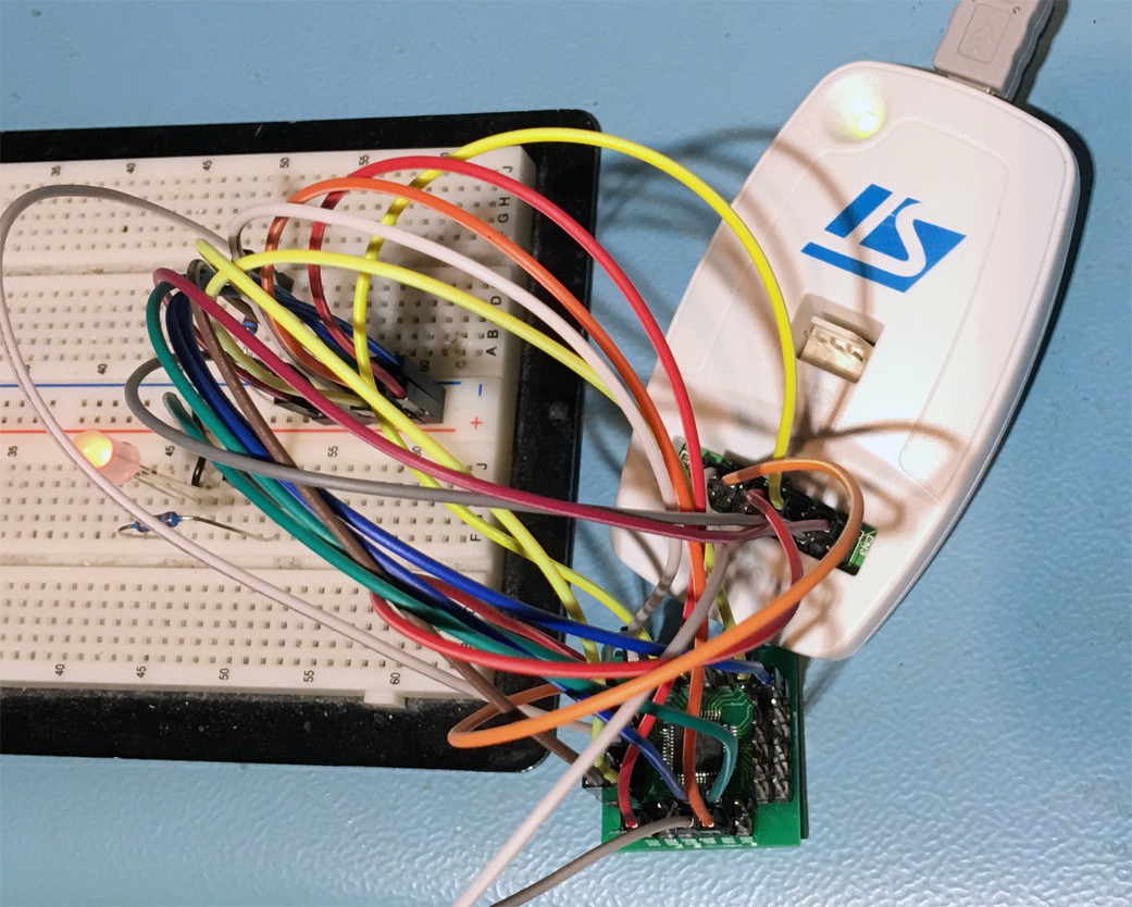
All these wires are just for VCC, GND, and for the programmer and boot configuration:
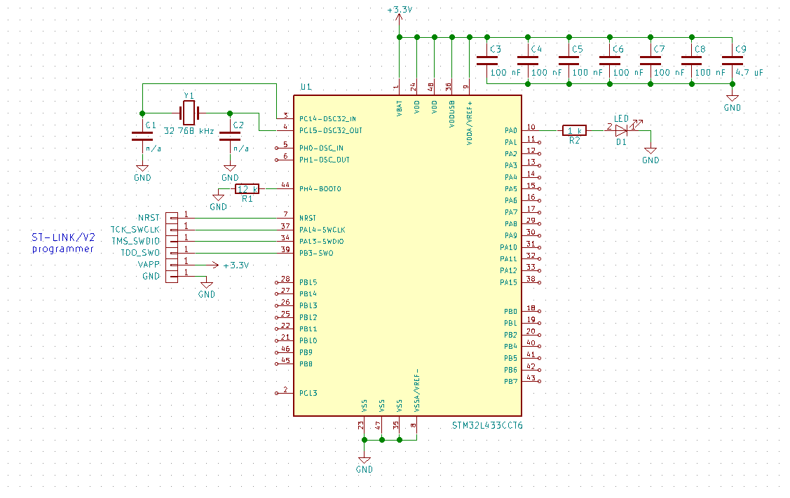
The 100 nF and 4.7 uF capacitors are directly soldered on the back between the pin headers. I configured the clock for the maximum allowed frequency with the internal oscillator, 80 MHz, and the power consumption was only 10 mA. The capacitors C1 and C2 depend on the crystal. I've used the ABS07-120-32.768kHz-T crystal from my RTC test for my Nixie tube clock, but omitted the capacitors and looks like it works, because they are in the picofarad range and my test setup might have already enough parasitic capacitance.
After this I added a 32.768 kHz RTC crystal to pin 3 and pin 4 and configured the clock for 48 MHz and one pin for PWM output with timer 1 in CubeMX (don't forget to add a line like "HAL_TIM_PWM_Start(&htim1, TIM_CHANNEL_1)", otherwise there is no output), and I could measure a very accurate 24 MHz signal, better than 0.1 % accurate, the resolution of my scope.
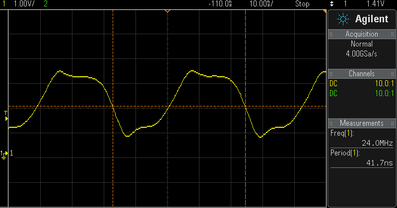
Usually you can't use the slow RTC clock to generate such a high frequency, but the internal high speed RC clock can be configured to get calibrated automatically by the low frequency RTC clock, which is a neat feature and eliminates the need for another external high speed crystal, even if you want to use the USB interface.
Then I tested the new 128x296 3-color ePaper from Cystalfontz, 2.9". The website provides datasheets for the display, the breakout board and sample code for an Arduino. Unfortunately the naming of the pins different is different, but similar enough to guess what is meant:
| Arduino code | breakout board PDF | display PDF |
| EPD_BUSSEL | INT_SEL | BS1 |
| EPD_READY | BUSY | BUSY |
| EPD_RESET | RESET | RES # |
| EPD_DC | DC | D/C # |
| EPD_CS | SS | CS # |
| (SPI transfer) | MOSI | D0 |
| (SPI transfer) | SCLK | D1 |
Would make life easier if they would use the same name everywhere.
The bus selection pin was always low in the source code (for 4 wire SPI mode), and on the breakout board is was soldered to GND anyway, so you can control the display with 6 pins from a microcontroller (and VCC and GND connected).
This is how it looks like, with the demo code ported to the STM32 microcontroller:
As you can see, the black fades to grey when the red image is updated, doesn't look as good as the 4.2" display from Pervasive Displays. But the image with the cat was the same grey when I got it, so I guess there is nothing wrong with my source code. I'll contact Crystalfontz, maybe they have better lookup table (LUT) data, because unlike the examples from Pervasive Displays, with this display from Crystalfontz the LUTs are sent from the application.
Discussions
Become a Hackaday.io Member
Create an account to leave a comment. Already have an account? Log In.
Cool project! Where did you find the STM32L433CCT6 eagle symbol? Made it yourself?
Are you sure? yes | no