 Jeremy Gilbert
The last 2 weeks have been a big of a slog for Makernet. I'm in that obnoxious phase where a ton of stuff has to get done but there isn't a whole lot of new wiz-bang stuff to show for it.
It kind of reminds me of this picture:

Anyway, last weekend I accomplished a major but somewhat unfulfilling task: I successfully stabilized the rotary encoder board's logic.
The rotary encoder board looks like this:
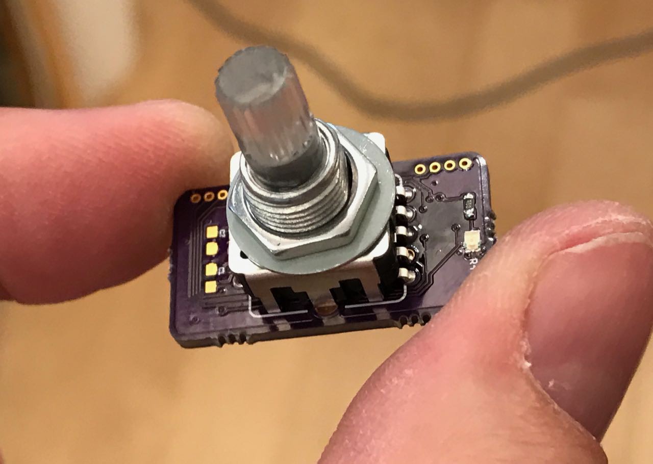
I had noticed for a long time that my rotary encoder was not nearly as stable as it is on the Teensy or in other projects I built. I had been treating the Arduino Encoder library as a bit of a black box, but this was coming back to bite me. I was seeing skipped steps and other unexplained repeating pattern glitches. Initially this didn't bother me much because as a proof of concept, it still worked.
But I'm rapidly getting out of proof of concept mode and quality starts to matter. Over the weekend someone reached out to me on Twitter asking if they could try out some of my boards for a project they are working on. So I now needed to get the rotary encoder far more stable since it would be leaving my workshop and going out into the world.
I have to admit that I basically never really "grokked" how the rotary encoder works. Yes, I understand the principal, but knowing the theory is quite a bit different than actually intimately understanding the various state transitions. I had been trying to get away with not knowing them and treating them like a black box. But this challenge finally tipped me over the edge since no one on the Teensy forums seemed to have any idea what might be going on.
So if I wanted a high quality rotary encoder circuit board, basically no one was going to do this for me. I had to do it myself.
People sometimes say "why do we need Makernet"? For instance, they point out that there is a lot of example code out there for a rotary encoder. Why would a person want to buy (or make from source) a single component that connects a rotary encoder onto a shared network bus? Even if it was less than $10 in parts? Well, one of the reasons is that rotary encoders are harder than they look. They get glitchy!
In fact, all bits of hardware actually are harder than they look. And if I'm some random interaction designer working on a project where I think it might be nice to experiment with adding a rotary encoder to my device, I don't want to spend a weekend learning the gross details of this esoteric device. Its the same reason why the ArduinoCore is so useful at getting people out of the weeds. Sure, digitalWrite() can be replaced with PORT register calls. But doing that forces you to worry about implementation that you'd rather not have to deal with. It takes your head out of the game and slows down your innovation and your idea generation/iteration.
Anyway...
I digress.
So, the Makernet rotary encoder design needed to be stabilized and de-jittered. After a painful process struggling with my oscilloscope, I decided to try my Saleae Logic 8. This little tool is super useful and frankly probably the most useful diagnostic device I own. After setting up a test rig, I started looking at traces especially under high speed.
What you see below is both an analog interpretation of the pins as well as the controller echoing back when its interrupt were firing and what the MCU thought the rotary encoders A and B signals were.
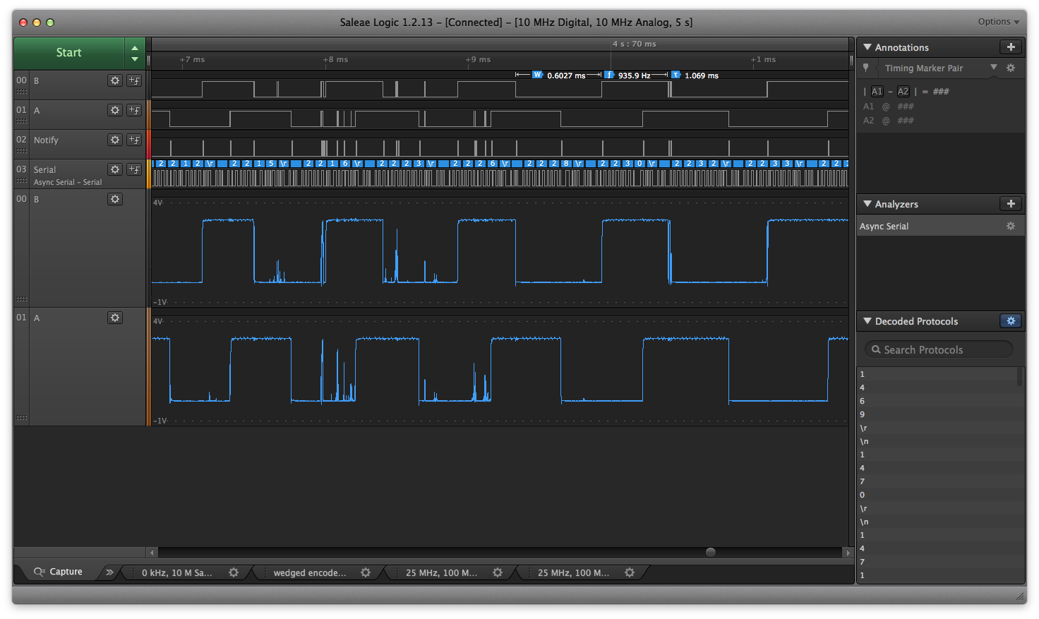
I quickly discovered that there were bizzare corner cases that most rotary encoder code-bases or tutorials don't handle or even bother to tell you about. For instance, the "recommended" way to read an encoder is with an pin change interrupt. But say your encoder is noisy and it bounces around a lot. Its possible that a LOW->HIGH bounce will trigger the interrupt several times, and that by the time the interrupt code reads the pin state it will have temporarily bounced back LOW. That means that for the next few microseconds, maybe longer, the code's state machine thinks that the pin is LOW when its really high.
This "gap" may not be detected until the next interrupt is fired for the other pin changing. And that is actually a bigger problem than it sounds.
Rotary encoders are tricky. The key to the state engine is to detect the ORDER that the A and B pins change to know which direction the rotary encoder is spinning. So if you miss a transition on one pin that you don't recover until the other pin changes, you've lost some key information that can get the state engine confused and thus introduce jitter.
Of course, I knew none of this on Friday night when I started stabilizing the device. I had to learn it along the way.
Here is a trace of exactly this problem:
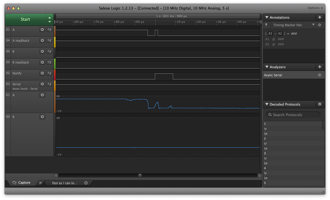
In this case, the interrupt fires once on a A HIGH->LOW transition. But by happenstance, at the moment that it reads the A pin, its bounced back up to HIGH. Therefore, for a practical eternity, the code has the state of the A pin wrong!
This is the sort of glitch you can only really detect with a logic probe.
The solution was to add periodic reads of the pins in addition to the interrupt logic. Empirically, I determined that the even at top hand speed, the encoder's digital signals will be stable for at least 0.1ms. Therefore, I used that as my timing for the extra pin reads.
The following trace show the problem fixed. The logic probe was essential because it let me verify that the fix I thought would work actually did its job in the erroneous (and hard to trigger) test case scenario,.
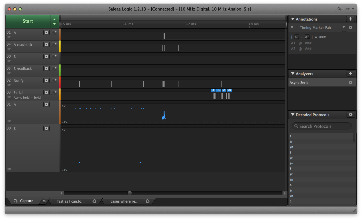
Here you can see the notify pin showing the interrupt activity, and just around the +6.6ms mark, it correctly changes its internal state of pin A to read low.
Once in place, this cleaned up the reads significantly and resolved most of the issues.
Now, you may ask why I didn't just add a 0.1uF cap to debounce the encoder. In fact, if you look closely, you can see that I anticipated the need for such caps when I designed the board. The reason is that a 0.1uF cap is actually a bit too much capacitance. It slows the reads down and I found that the interaction appeared to miss steps when the user was really spinning the controller a lot.
Probably for most hacker projects, this would not be an issue. However, I want Makernet to really be useful for a wide variety of scenarios ranging from game controllers.
Based on my tests, I think a 0.01uF capacitor is probably a better tradeoff between de-bouncing. This is not a SMD part people usually think of and it wasn't added on my test board.
So basically I plan to conquer the issue with a combination of hardware and software.
Is my project any more worthy as a result of doing this work? I'm not sure. At least I learned something and I'm more proud of the work I'm doing. :)
Discussions
Become a Hackaday.io Member
Create an account to leave a comment. Already have an account? Log In.