 Frank Buss
For a smooth transition of digits and for adjusting the brightness, I plan to use PWM. For testing this, I wrote some VHDL code, with which I can create 10 PWM outputs, each one with three 32 bit counters: one for an initial off-time, one for the on-time and one for the final off time. The initial off-time is useful, if you want to turn on the PWMs phase-shifted, to avoid big current spikes if you turn on all PWM outputs at the same time. All 30 counters are running in parallel and clocked with 25 MHz (I love FPGAs). The reload values of the counters can be programmed via an SPI interface. For testing the functionality, I wrote a VHDL testbench. In a testbench you instantiate the component you want to test, simulate inputs and check the outputs. This is a little bit simpler: I just simulated the inputs, and looked at the outputs in the wave display of ModelSim to check if it is right:
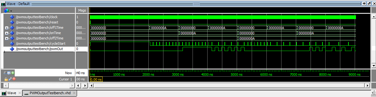
And looks good. I tested all 8 combinations of setting off1Time, onTime and off2Time to 0 or 10. In the last line you can see the PWM output signal, and the phase relative to the cycleStart impulse.
With this FPGA configuration I can now test different PWM frequencies, down to seconds cycle time and up to MHz. For example with a PWM frequency of 6 kHz, I can implement a PWM resolution of 13 bits. This is sufficient for a smooth fading, which is tricky, because it has to be exponential: If it is dim, the human eye detects small changes much better than when it is bright, so you need small steps when it is dim and larger steps the brighter you get, for an apparently linear experience. I used the formulas as described here and implemented it in an Arduino sketch.
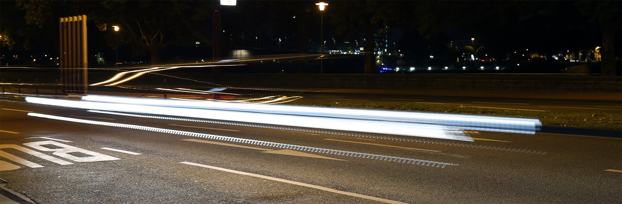
You might think a PWM frequency of 100 Hz is sufficient, but there are studies that you need at least a few kHz to avoid seeing dots when moving your eyes fast (saccade). Once I photographed a car headlight with long exposure and I could calculate the PWM frequency of the LEDs to be 100 Hz. This can be really annoying in traffic, when you move your eyes.
 This is the PWM signal which the Arduino sketch creates, tested with LEDs:
My camera is not very good, in reality it looks even better.
Full source code for the FPGA project and the Arduino sketch is available in github. For the FPGA board I've used this one which you can get from eBay for 33 EUR, an USB blaster FPGA programmer clone included. Works great, but there are even cheaper FPGA boards, if you don't need the VGA output etc. The Arduino is an Arduino Nano clone, which you can get from eBay for EUR 2.39 shipped. Crazy how they can manufacture and ship it for such a low price.
Next I'll develop the high voltage driver for the Nixie tube and then test the PWM signal with the tubes. Some people suggested that Nixie tubes can't be controlled with such high PWM frequencies, because the gas in the tube needs some time to ignite, and you can't reduce the duty cycle too much, otherwise the gas doesn't stay ignited. Will be interesting to see how this works out. There were also some concerns that the tube ages faster when pulsed with PWM, but I asked Peter from Tubeclock.com about it and he says it doesn't matter much.
Discussions
Become a Hackaday.io Member
Create an account to leave a comment. Already have an account? Log In.
It's interesting that I have come to similar conclusions during the design of #DYPLED.
I remember I settled for about 6KHz, which got reduced to 3KHz with the divide-by-two circuit.
Are you sure? yes | no