 Jon Buford
I've been working through the schematic and adding the final bits before going to the PCB layout. One feature that I forgot to factor into costing so far was the parts for preventing a power conflict if our board is powered and the Pi also is powered from a USB source at the same time. The HAT spec does have a solution for this. In our case, we want to be able to either power the board from the Power module or from the Pi (ideally), so we need to take that recommended spec and tweak it a bit.
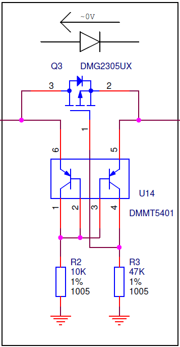
Looking at just preventing a power conflict on the 5V, which is the original HAT spec design, it uses one P-Channel MOSFET plus a matched PNP transistor pair.
This would work if we only are thinking about powering the Pi via 5V from our HAT. We have another condition of powering our board from the Pi, at least the 5V and 3.3V. Looking at using a switch to bridge the power, options with enough current handling capacity are quite expensive. It seems like the best option is to do a single set of jumpers between the Pi and the HAT on one 5V and one 3.3V pin. This will be normally unpopulated, and will need to be well labeled to prevent accidental usage.
On that note, the extra components involved probably end up breaking the cost limit that we need to hit with this design, but it does open a simple option. We will do two designs, one that has the Power module and the other without. This allows for a lower cost for the unpowered version, and we might be able to fit in a higher spec controller or something like that. Dropping the VIN power means that we can use the 28-pin version of the IO module connectors, which also reduces the cost. To maintain the compatibility with the HAT spec, we will still need to keep the full 40-pin connector to the Pi, so that will drive the overall size limit we can have.
Discussions
Become a Hackaday.io Member
Create an account to leave a comment. Already have an account? Log In.