 Jon Buford
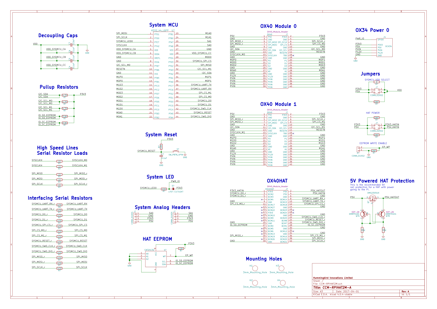
And this is the end result schematic. Some notes on how things turned out:
- In the jumpers section, you can see that there are DNP or 0 Ohm resistors used in parallel to a pin header. This will give users a choice of either using jumpers with a pin header or to solder their choice without pin headers. All of these except for the one 0 Ohm resistor will be unpopulated to start with.
- We are assuming that if the user is using the system as a powered system, the 5V and 3.3V power is coming from the HAT for the board. This means that to program the system MCU, power will need to be applied to the Power header (at least 3.3V) or the user will need to configure the power jumpers to run the HAT off of the Pi power.
- If the power from the Pi is enabled, it is up to the user to NOT connect those supplies to the Power header. It is possible to cause a power conflict if this is enabled and burn out things. It would be possible to run 3.3V and 5V from the Pi with 12V and VIN coming from the Power header. Everything should be OK as long as there isn't a conflict with the grounds.
- I'm trying a new way to define the decoupling caps. I don't like the way that they are traditionally banked together without a good reference to where they should be placed on a board. The way they are done here *should* give feedback on the layout which caps belong to which pins. These ideally are placed close to each pin they supply.
So, I don't have a final BOM created yet for this, but I'm guessing around $3-3.50 in quantity. This would make it suitable for something around a $12-15 retail. I need to see what the non-powered version clocks in at, but I think we can shoot for that as a $10 retail price.
Next is to select the footprints and then do the PCB layout. The first step will be to put the parts on the board and import the board layout from the 3D model for placement of connectors.
Discussions
Become a Hackaday.io Member
Create an account to leave a comment. Already have an account? Log In.