After I saw that JLCPCB can manufacture 10 boards for $2 with a lead time of 2 days and express DHL shipping (I'm not actively promoting, just amazed and a bit concerned about their business model) I decided to design and order the electronics for the watch winder.
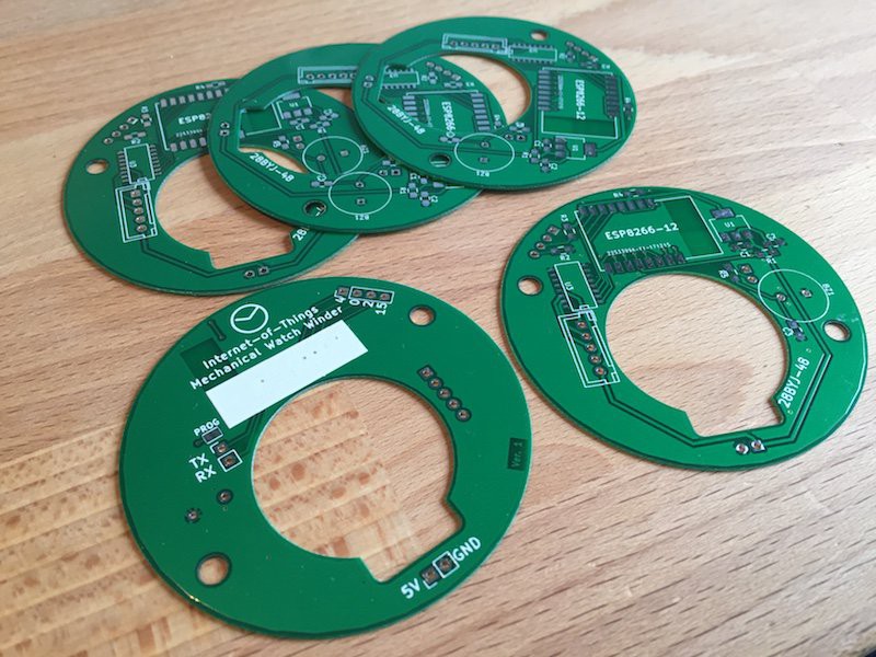
These are the boards:
Assembled it with some minor mistakes and temporary cables for power and programming:
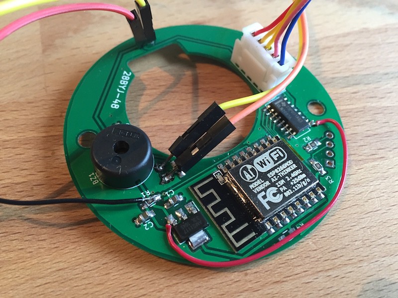
Red cable is because I connected to the common pin of the darlington array to ground, it should've gone to 5V (short). The stepper didn't turn. Amazingly the thing just heated up, but didn't release its magic smoke. There's probably about $5-8 worth of electronics as of now.
The "motor driver" (darlington array) that came with the stepper motor was slightly too big for the PCB (16PDIP package), so I ordered some free samples from TI, I got 5 smaller versions (SO-16 package) of the ULN2003A which perfectly fit the available area.
The stepper motor connector was salvaged directly from the driver board it came with.
Since I had some space left I added a buzzer and broke out some pins just in case I wanted to add some features. I was expecting this to not be the first and only PCB for this project. I also added a large whited-out silkscreen area to write on (IP address, name, product code...) this will be gone too in the next version.
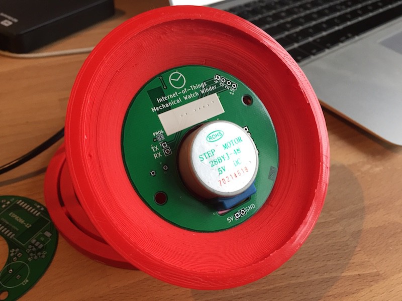
This is how the PCB will be mounted on the bottom of the winder:
The Internet of Things Mechanical Watch Winder prototype winding one of my watches with me controlling it via a Node-Red interface:
The frame squeaks quite a lot, some parts need to be modified, it's incredibly annoying after a couple of minutes...
Discussions
Become a Hackaday.io Member
Create an account to leave a comment. Already have an account? Log In.