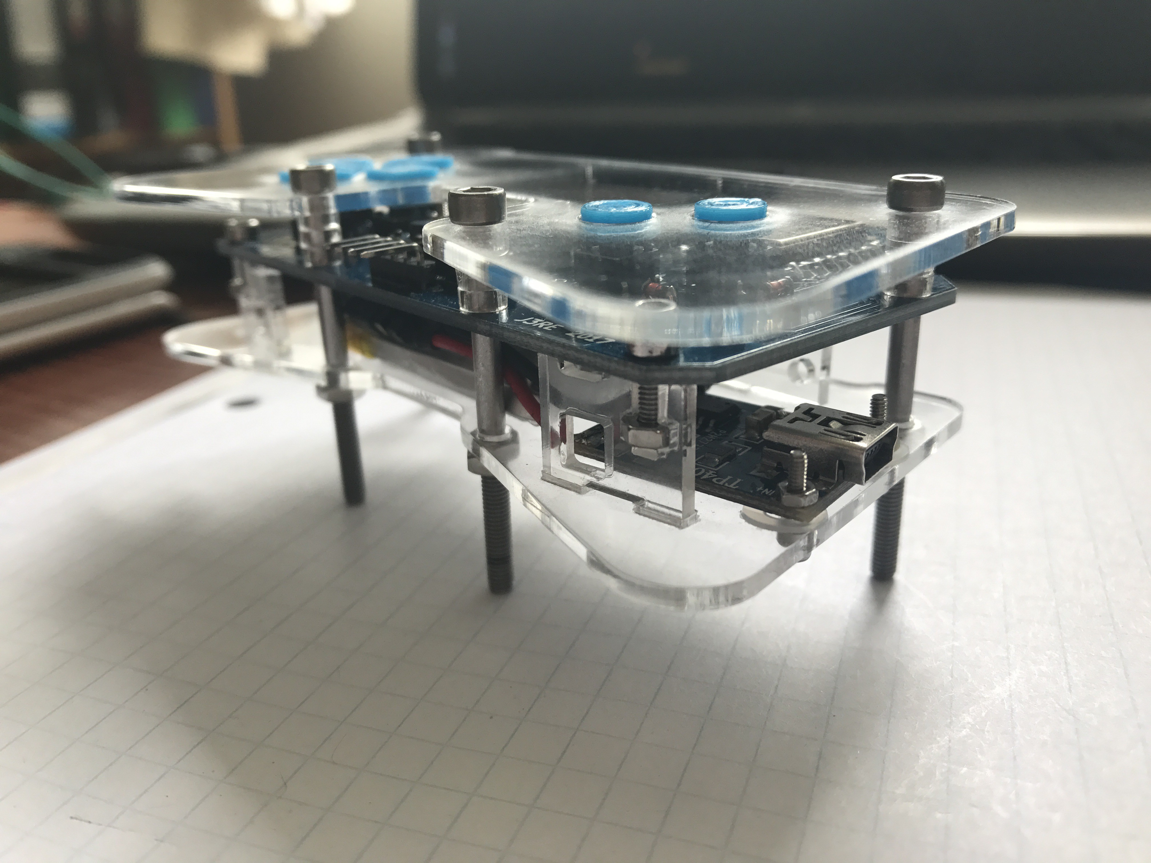
I soldered the PCB and assembled all the parts. I still need to cut the screws to the right length, but apart from that the hardware is finished. The PCB is functional, but there are some things I would change next time. For instance:
- label the individual pins of the connectors
- label the "reset" and "flash" buttons
- use an 0805 diode package instead of an 0805 resistor package for diodes (on the PCB is no mark how the diode should be installed)
I will make an example code, which shows how to use the buttons and control the LEDs. The code should be on github in a week or so.
PS: If someone near to Austria wants a PCB, drop me a line, I don't need all of them.

 Jeremias
Discussions
Become a Hackaday.io Member
Create an account to leave a comment. Already have an account? Log In.