Close
0%
0%

Cat-644

An 8-bit computer based around an AVR ATMega-644 and junk-box SRAM.

Similar projects worth following
The C-644 is an 8-bit computer using the Atmel ATMega-644 microcontroller as its CPU.

Processor: Atmel ATMega-644 @ 20 Mhz (approximately 20 MIPs)
Program Memory: 64k Flash.
Data Memory: 4k internal SRAM, 128k additional SRAM
Video: 64 color VGA output. Timings for 640x480. Actual resolution 256x240 or 512x240.
Sound: 8-bit PWM at approximately 11 khz.
Storage: 1GB SD Card, removable
Communications: RS-232 at 115kbps, partially implemented Ethernet
Input: PS/2 Keyboard (works with many USB keybord via passive adapter)

All of the above, has been constructed and is working on the V1 prototype. Ethernet has some work left to do.

Software:

Cat-OS is in development.
Bytecode interpreter for SRAM-based programs in development. (Current estimate 1 - 1.5 MIPs (16-bit!) )
Hardware Rev 2 is in development!

Hardware Introduction

The CAT-644, is a simple computer using a 20 MHz ATMega644 microcontroller as its CPU. I am using the DIP-40 package, making it breadboard and hobbyist friendly.  Large sections of this project can be built and run entirely on a breadboard, without any soldering.  The ATMega644 offers four 8-bit GPIO ports, with each pin configurable as an input (with or without internal pullup resistors) or an output.  Many pins also have special hardware functions that can be enabled.  

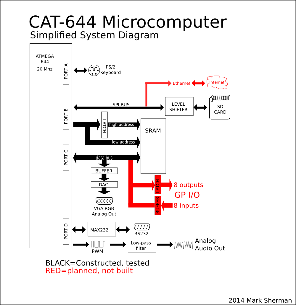
This is the current use for each pin in the CAT-644:

  • PORTA
    • A.0 through A.2 are currently unused!  The possibilities are endless!
    • A.3 is the SD card enable line (explained in Disk section)
    • A.4 is the VGA DAC enabled line (explained in Video section)
    • A.5 is the Address 16 line (explained in RAM section)
    • A.6 is PS/2 data signal  (explained in Keyboard section)
    • A.7 is the PS/2 clk signal
  • PORTB
    • B.0 through B.7 are used as an 8-bit address bus for memory operations
    • Alternatively, pins B.7, B.6 and B.5 make up the SPI bus.  This function is used when talking to the SD card.
    • B.4 and B.3 are outputs that can be controlled by 'Timer 0' of the AVR.  The timer counts clock cycles, and when the right value comes up, these pins can be controlled w/out software intervention.  This is used to make the address bus count faster than the CPU would normally allow for.  (explained in Video section)
  • PORTC
    • B.0 through B.7 are used for the data bus while doing RAM operations.
    • Some PORTC pins are also used for JTAG.  I am not using JTAG, but mention it, as it just be explicitly disabled to avoid it from interfering with normal PORTC operation.
  • PORTD
    • D.1, D.0 RS-232 port (see Serial section)
    • D.2 Ram output enable
    • D.3 Ram page latch (see RAM section)
    • D.4 VGA Vsync
    • D.5 VGA Hsync. This is also a timer 1 output pin.
    • D.6 RAM Write Enable
    • D.7 Timer 2 output.  This is used to generate PWM audio signals.  (See Sound section)
Read more »

  • 1 × Atmel ATMega-644 20 Mhz 40-pin dip
  • 1 × Hitachi H628128LP 128Kbyte SRAM 32-pin dip, 100ns or faster obsolete, but many substitions are possible,; it is a very common pinout
  • 2 × 74HCT244 bus transceiver HCT is required for at least one of these. (HC not guaranteed for SD card level shifter)
  • 1 × 74HCT573 octal transparent latch HC may be substituted
  • 1 × LM7805 5v regulator LM317 may be used with minor modification. Heat sink recommended. (I used a piece of scrap metal)

View all 17 components

  • Continuing work on KittyOS

    Mars03/21/2019 at 21:17 0 comments

    For the March 2019 Retrochallenge, I am continuing to work in kittyOS.  I accomplished a lot last time, and am adding more this month.

    For full details, check my personal webpage http://mwsherman.com/rc2019/03/

    The goal is to turn the CAT-644 into a 'real' computer.  And what I mean by that, is eventually I want to be able to turn it on, open a text editor, write some source code, compile, and run it, without turning on my PC.  To do this it needs a real operating system.

    The Unix model is everything is a file.  This has been copied to death.  I am intentionally trying something different.  Instead, everything is a device.  A special device, a mux, lets a program select thru a collection of devices.  The plan, is the sdcard filesystem, is just a tree of virtual muxes, eventually selecting virtual block or char devices containing data.  You could call them directories or files.  But you don't need a traditional filesystem to get started;  The basic setup is a single mux containing a single device such as a serial port.

    Hardware Drivers

    The following is all working in the kittyOS hardware drivers.  Not all is bound to the OS by syscalls, but the driver's work on their own:

    • Graphics
      • 248x240  64-color VGA graphics (with 640*480 timings)
      • Text output w/ scrolling
      • Sprite render
      • smooth 1px horz/vertical wraparound scrolling, with 'invisible' region
      • FAST (50% cpu) and SLOW (90% cpu) modes
    • Serial
      • Up to 115k baud
    • SDCard
      • recognize SD (not SDHC, SDXC) up to 2GB
      • read/write block
    • PS/2 Keyboard
    • Audio is supported (and tested) by the hardware, but not yet implemented in kittyos

    Implemented and Working:

    • Device driver tree
      • Mainmux device supporting:
        • character devices
          • PS/2 keyboard
          • VGA console
          • serial port
          • SPI port
          • planned: A 'file' is just a seekable chardevice accessible thru a tree of virtual muxes, stored on an sd card.
        • block devices
          • sdcard
            • init
            • read/write blocks
            • sdcard is controlled as spi device thru spi driver
        • mux devices (mux is a collection of devices)
          • the mainmux is the device thru which all other devices are reachable
          • muxes can switch other muxes
    • 16-bit virtual machine interpreter
      • 16-bit accumulator-register machine
      • fastest possible dispatch: One 16-bit reg-reg arithmetic instruction per 6 AVR cycles (Can this be beat?  I've looked everywhere for a faster interpreter.  I can do in 8-bit machine with 5 cycles, but many programs want 16-bit math anyway)
    • Handle-based memory allocator with automatic swapping between AVR internal memory and external SRAM.  (possible future support for disk-swapping or load-on-demand)

    Planned:

    • interpreter-accessible syscalls for handle access
    • Swappable handles containing code
    • Storing chardevices on sdcard mux (finally 'files')
    • Syscalls for sprites
    • Audio support (eventually)

  • Operating System (kittyOS)

    Mars09/04/2018 at 18:55 5 comments

    I have started developing a 'proper' operating system for this computer.  I am doing it for the 2018/09 Retrochallenge.  http://mwsherman.com/rc2018/09/

    Goals:

    • Run native AVR programs in flash
    • Run interpreted programs from SRAM
    • Handle-based memory allocator:  allow swapping memory from internal AVR memory to external memory
    • Simple filesystem on SD card

    Currently running in kittyOS:

    • Hardware initialization
    • Serial port as a 'char device'
    • I/O devices abstracted:  program running on the serial port could be switched to another device (if there was another device implemented to switch to!)

    Existing code from the original cat1.c demo program: (to integrate in kittyOS)

    • VGA driver (writable as char device for text; special calls for drawing sprites or pixels)
    • SD Card driver (read/write linked lists of chained blocks)
    • PS/2 keyboard driver (read only char device)
    • Sound driver

    Existing code run in simavr, but not tested on real hardware yet:

    • 16-bit interpreter
    • memory allocator ( can't use avr libc malloc, as I need allocation logic that knows about bitbang xram)
    • task swapping

    Todo List: not implemented anywhere yet

    • filesystem directory (those linked list of disk blocks need a name... now you have a proper 'file')
    • memory swapping  (SRAM should just be a cache for XRAM structures)

  • Accumulator Machine Implementation

    Mars03/11/2017 at 21:11 3 comments

    I've begun work on the virtual machine interpreter that will run on the Cat-644. I am writing it as a separate Atmel Studio project, as I could see this being useful outside of this.

    The interpreter assumes that once it is invoked, it will never exit. Any interrupts already 'hooked up' to C functions will still operate normally. The interpreter can call out to single user-defined function called 'syscall.' Syscall is free to call out to other C functions, as the C stack will be available and left intact for this purpose.

    simavr Windows Port (small side project)

    I am mostly a Linux user. An exception to that rule is AVR development. I really like Atmel Studio's IDE, especially the AVR simulator in single-step mode. Every hardware peripheral is right there, clock by clock, in a nice graphical way. You can use gdb for this, but it is simply more convient to press the single-step key and watch port registers turn on and off. It was extremely useful for debugging the PS/2 keyboard and VGA signal code. What is not good about it is the lack of serial port support. You can watch a byte appear on the serial register, and you can poke 1 byte at a time into the register, but it is a pain to do so. This is where the simavr open source AVR simulator really shines. It has full serial port emulation, and on linux even gives you a pty you can attach a terminal to. When developing a bytecode interpreter, I want both: I want to single-step through code in Atmel Studio on Windows, especially when watching things like that stack frame and or studying the timings of different routines. And then, I want to run a program at full speed, and interact with it like it is on a serial port. What I needed was simavr on Windows. SImavr had mingw support, but I didn't want to set up mingw just for this, and I was curious what it would take to get it to run on Visual Studio. I got it working well enough for my current project: https://github.com/carangil/simavr-visualstudio

    Small Interpreter

    The goal is for the interpreter handlers of all of these instructions to fit within 256 instruction words on the AVR. This is because of the way I am fetching these instructions. All the instruction handlers fit on a single 256 word page of flash, so they all have the have MSB address. This is so the ZH register can be set up once. The instruction bytes themselves are directly loaded into the ZL register, and an IJMP is performed. At least all the entry points for all the instructions must fit in this page: If certain instructions are long, the handler can jump out another routine.


    Registers

    The virtual machine has 4 16-bit registers, labeled A, B, C and D.

    Register 'A' is the special Accumulator register, and most instructions require its use. This is to keep the number of possible instruction encodings as small as possible. All instructions that don't have immediate data are 1 byte long, and instruction that need data are followed by 1 or 2 bytes.

    There is a stack, managed by the 'Y' 16-bit index register of the AVR. This is separate from the C stack. This doesn't have to be, but this is the case at the moment.

    Available Instructions

    1. LI (Load immediate) Can load an immediate 16-bit value into any register A,B,C,D
    2. Swap: Swap the contents of A with either B,C or D
    3. Arithmetic Instructions: Performs an operation between registers B,C,D and A, and stores result in the accumulator (register A)
      1. add
      2. sub
      3. subr (not yet implemented: performs reg-=A instead of A-=reg
      4. and
      5. or
      6. xor
      7. cmp Does a trial subtraction, but doesn't modify registers. Sets internal flags.
      8. adc: Add-with-carry, allowing 32-bit and higher math.
    4. Syscall The C function 'syscall' is called, with 2 16-bit arguments. The first argument is the contents of A, and the second argument is the contents of B. The return value of the C function is returned to the interpreted program in register A. The rest of the registers are unmodified. Complex, operating-system like operations will be done here, in native AVR code, as opposed to being code in the...
    Read more »

  • Accumulator Machine

    Mars02/04/2017 at 21:57 0 comments

    After sitting down and playing around with syntax I think I've figured out what a programming language for an accumulator machine would look like. If you are familiar with FORTH or with RPN calculators, this makes a very good langauge to natively program a stack machine in:

    C or BASIC:  Z = X + Y
    FORTH: x @ y @ + z !
    
    stack machine:
    
    push Xaddress  // x
    load // @
    push Yaddress //y
    load // @
    add // +
    push Zaddress // z
    store  //!

    With the above snippet, forth and stack machine assembly langauge have a 1 to 1 correspondence, and the same is true for most forth expressions.

    How do you generate code on a standard register machine? One way to do it, is to keep track of which register is the top of the stack as code is generated. Push a value? Put it in A. Push a second value? Put it in B. Add the top two values? A and B are the top, so add them, keep track of which one is on top. If you need more values than registers, you can spill to the stack, and still keep track:

    FORTH | assembly  |   stack register allocation
    x     | mov a, @x |   a
    @     | ld a	  |   a b
    y     | mov b, @y |   a b
    @     | ld b      |   a b 
    z     | mov c, @z |   a b c
    @     | ld c      |   a b c
    w     | mov d, @z |   a b c d
    @     | ld d      |   a b c d
          | push a    |  (real stack) b c d
    k     | mov a, 2k |  (real stack) b c d a
    @     | ld a      |  (real stack) b c d a
    +     | add d,a   |  (real stack) b c d
    +     | add c,d   |  (real stack) b c 
    +     | add b,c   |  (real stack) b
          | pop a     |   a b
    +     | add a,b   |   a
    

    If you switch to an accumulator architecture, instead of operating on the top of the stack, the cpu operates on the accumulator, and whatever the top of the stack is. There are a few options to deal with this. First, the simplest is pretend you have a register machine, and as a post process, use swap instructions to put operands into the accumulator.

    I wanted to look and see what a forth-like language that explicitly supported an accumulator would look like. I came up with a stack-accumulator abstraction. The above stack-register allocation scheme will be used with registers B,C,D, will spilling onto the hardware stack. All math operations will be between the accumulator, and the current top of the stack.

    I added the symbol '%' to represent the accumulator. If '%' is prepended to a number or constant, it means that push operation puts the number in the accumulator instead of the stack. When doing this, the current value in the accumulator maybe stored in the stack.

    %4 3 +    // put 4 in accumulator 3 on stack, add accumulator and stack

    The above %4, will overwrite whatever was in the accumulator. Sometimes you want to preserve what is in the accumulator to the stack:

    %1 %%4 3 + +   
    breaks down to:
    
    %1:  put 1 in accumulator, overwriting whatever is there
    %%4:  put 4 in accumulator.  the '1' is displayed to the stack
    3: put 3 on the stack  
    +: adds accumulator (4) to top of stack (3)
    +: adds accumulator (7) to top of stack (1) giving 8, left in accumulator.
    

    There are a few other symbols needed:

    @ : load address on top of stack to top of stack (same as forth)

    %pop : move top of stack to accumulator

    %@: load address in accumulator to accumulator

    %%@: load address in accumulator to accumulator. the original address that was i the accumulator is preserved on the stack

    dup: copy top of stack to top of stack

    %dup: copy top of stack to accumulator

    WIP, to be continued

  • Virtual Instruction Set Candidates

    Mars02/01/2017 at 07:32 2 comments

    It is time for me to write the virtual machine interpreter for this project. In a previous project log I once went over a fast instruction dispatch mechanism. I'll go over that briefly here: One goal was to have single-byte instructions. Reading 1 byte internal SRAM on the AVR takes 2 clocks. So, at a minimum we have this:

    ld Reg, X   //2 clocks, fetches 1 vm instruction
    

    This loads a 1 byte instruction from where X is pointed. Remember, X is a 16-bit register made up of 2 8-bit registers. Using X as an instruction pointer for the VM has the advantage the there is special hardware to increment (even with carry) the 16-bit pointer at the same time we do the fetch. So, we have:

    ld Reg, X+ //2 clocks, fetches 1 vm instruction, increments instruction pointer for next instruction

    Now, we need to decode the instruction to a handler. There are many ways to do this, one is a lookup table. I decided to have the instruction simply be the value of the lookup table by making all instruction handlers aligned to 256 words. This means if a handler is located at 0x1300, it is the handler for instruction 0x13. The handlers are small, so there is a lot of empty memory between handlers. This was going to be accepted as a trade off, and there was going to be a small number of instructions. If we use the Z register to hold the address of instruction handler, and we preload the low byte of Z (ZL) with zero (and never write to it again), we can now fetch/decode the instruction with:

    ld ZH, X+   //2 clocks.  fetches 1 vm instruction, increments instruction pointer for next instruction, Z is a pointer to the instruction handler
    ijmp   (jump to address in Z)   //2 clocks to jump to the handler

    The AVR has the instruction IJMP which jumps to whatever address is in 'Z'.

    So what does a handler look like? Well, the handlers are short. Typical operations planned were things like 16-bit register add, with 2 operands. (Similar to x86):

    handler for add A, B:

    //AL and BL are #defines to some of AVR's registers
    
    add AL, BL   //1 clock add low byte
    
    adc AH, BH   //1 clock add high byte
    
    jmp fetch   //jump back to the instruction fetcher (2 clocks)

    Of course 'jmp fetch' can be replaced with a copy of the instruction fetcher, so we don't waste 2 clocks jumping to the fetcher:

    add AL, BL   //1 clock add low byte
    
    adc AH, BH   //1 clock add high byte
    
    ld ZH, X+   //2 clocks.  fetches 1 vm instruction, increments instruction pointer for next instruction, Z is a pointer to the instruction handler
    
    ijmp   (jump to address in Z)   //2 clocks to jump to the handler

    So in 6 clocks we can do one basic 16-bit mathematical operation, and set-up for the next instruction handler. The only problem is this depends on the instruction handlers being laid out in memory in a very wasteful way.

    Less waste.

    After leaving this project alone for a while, I realized if the number if instructions is kept low enough, all the instruction handlers might fit into 1 'page' of 256 instructions. This means instead of locking ZL to zero, and changing ZH, I can lock ZH to some properly aligned area, and change ZL. How many handlers can I fit here? The above 16-bit math handler comes out to 4 instruction words. 256/4 = 64. This means I can fit 64 simple handlers here. In practice I expect to be able to handle more than 64 instructions, because I don't need all instructions to be quite so fast. Simple register-to-register math ops should be made fast. More complex instructions that already need more time to execute, such as division, i/o, etc, can have a simple 1-word 'stub' handler in the aligned section that jumps-out to a larger space. For these complex instructions, the aligned handler section of code will act more like a jump table. This jump takes 2 clocks to execute, but on a slow division operation, it would probably not be noticable. If I can't get all the needed instructions to fit, I could also make one of the instruction handlers a 'prefix code', switching ZH to a second page of instruction handlers. The slower or lesser-used instructions...

    Read more »

  • Cat-644 Ser No. 3

    Mars11/24/2016 at 21:12 0 comments

    Kevin made me a second board with a few improvements. Counting my original prototype, this is the 3rd copy of this computer.

    The 3.3V regulator has an extra pad that can now accept both styles of regulators: 78xx series AND 1117 series LDOs. The too-close traces were moved. And row of header pins were added for all the (only 3) unused PORTA lines. Now every pin out of the microprocessor is easily accessible. Some pins, like the data and address lines are not explicitly brought out of the board, but just about every pin goes through a via at some point, so there are many places to cleanly solder a wire and grab a signal. (Clean... as opposed to tacking-on jumpers on the bottoms of all the ICs: putting a wire throgh a hole is much more sturdy.)

    I tin-plated my board, and I chose to use machined sockets, gold plated in the ones the local shop had in stock. My 20-pin sockets for the 74xxx logic chips have integrated bypass capacitors, so I left most of the bypass capacitor spaces blank.

    I discovered the the .1uf capacitor I originally had on the VSYNC VGA line is not necessary, at least with my current monitor, on this board.

    I am also making another change in the name of code optimization: I am switching the HSYNC and VSYNC signals. I don't need to change the board, just how the connector is wired up. (If someone discovers the .1uF vsync capacitor is necessary, one will have to be tacked-on somewhere, but you could do this in the wire harness itself if you wanted to.)

    Why am I switching these signals? The video interrupt is generated by Timer#1, and it has two channels, A and B. The timer is set to free-run to Channel A's value and reset to 0 when it reaches 636 (the number of clock cycles it takes between lines of video). When it resets, it also calls the video interrupt code.

    In my original version of the code the interrupt 'manually' pulled hsync low, first thing after the C interrupt 'header' code. After a while, I noticed that by chance Channel A's output pin happens to be the HSYNC line, so instead, I have it set up to pull sync low when the counter resets. Now when the interrupt starts, HSYNC had already been low for a few clocks. But now I want to push the HSYNC signal further into the past: I want the hsync to have been low for almost it's full duration before the interrupt even starts. First thing, I want the interrupt to pull hsync high, and then start outputting video as soon as possible. To do this, I need to use Channel B.

    Channel B can be set to pull the pins up and down at different time values than the reset value which Channel A is using. (I can't switch channel A and channel B behavior, as only channel A has the hardware to reset the counter and fire the interrupt: Channel B can only poke an IO pin on and off.)

    Channel B happens, by chance, to be the line I am using for VSYNC. So if I swap HSYNC and SYNC lines, I can now program the AVR's timer hardware to pull HSYNC low or high at a different part of the cycle than the start interrupt code.

    I have already swapped these pins on my connectors, and verified that the newly placed hsync pulse has horizontally shifted my display. Today is Thanksgiving, so I will probably stop for the day, but maybe this weekend I can finish the revised VGA driver.

  • Real Board!

    Mars11/16/2016 at 06:00 1 comment

    A coworker named Kevin recently started making homemade PC boards with a mill, and was going around the office to everyone he knows who does hobby electronics asking for work. I showed him this project, said I might try to do a layout soon and will be bugging him to waste some copper for me. To my surprise, a couple of days later he came back with a kicad layout. After a couple virtual iterations, a nearly fully assembled CAT-644 appeared on my desk wrapped in an anti-static bag.

    Tonight I pulled all the ICs out, and started testing connections, voltages, etc. I got brave enough to put my already programmed atmega I pulled out of the prototype, and plopped it in. I found one issue so far: Two traces were too close, shorting together two of the data lines to RAM. I found this with a little 'memory test' app I have. The app prompts over the serial port for a start address and a count. It will write 'count' number of pseudorandom bytes to ram starting at the specified address, and then read it back and display the XOR. This is how I found my troubles: The XOR value was sometimes 2 or 4, not the expected 0. This told me something was wrong with pins PORTC.1 and PORTC.2, and an ohmmeter told me they were stuck together!

    VGA output also works: I am running the 'simple' VGA loop, which just continuously displays the first 60k of RAM on the monitor. It's great for debugging RAM addressing issues: Pixels will be stuck, floating, or otherwise repeated. This with the above RAM test program makes it easy to diagnose connection problems.

    I have not tested:

    audio output (it's just one trace, so it's pretty foolproof)

    memory bank switching (again, its just one trace to do this. I know this pin isn't floating, since that would result in the screen unstably switching between the two ram banks.)

    SD card: I need to do a little careful probing here with my meter, but once I'm sure it's safe, I'll just have to plug a sd card in and see what happens.

    This is the board by Kevin. All the connections are on a right angle connector, and it happens to fit pretty much perfectly in a center groove of my breadboard.

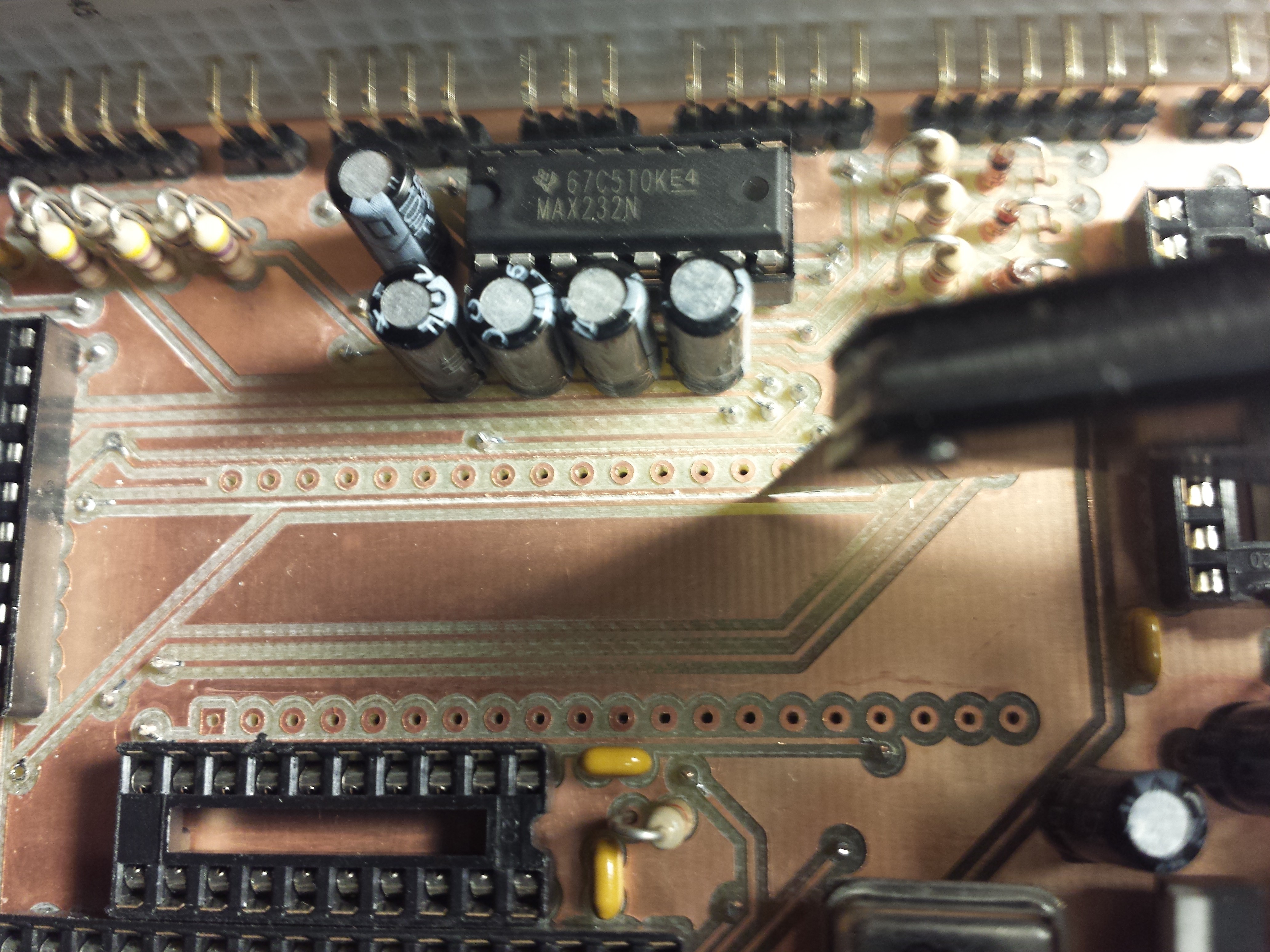
    Yep, the shorted traces were in the most annoying place possible: under the socket. Separating these two traces are on the top of the kicad todo list.
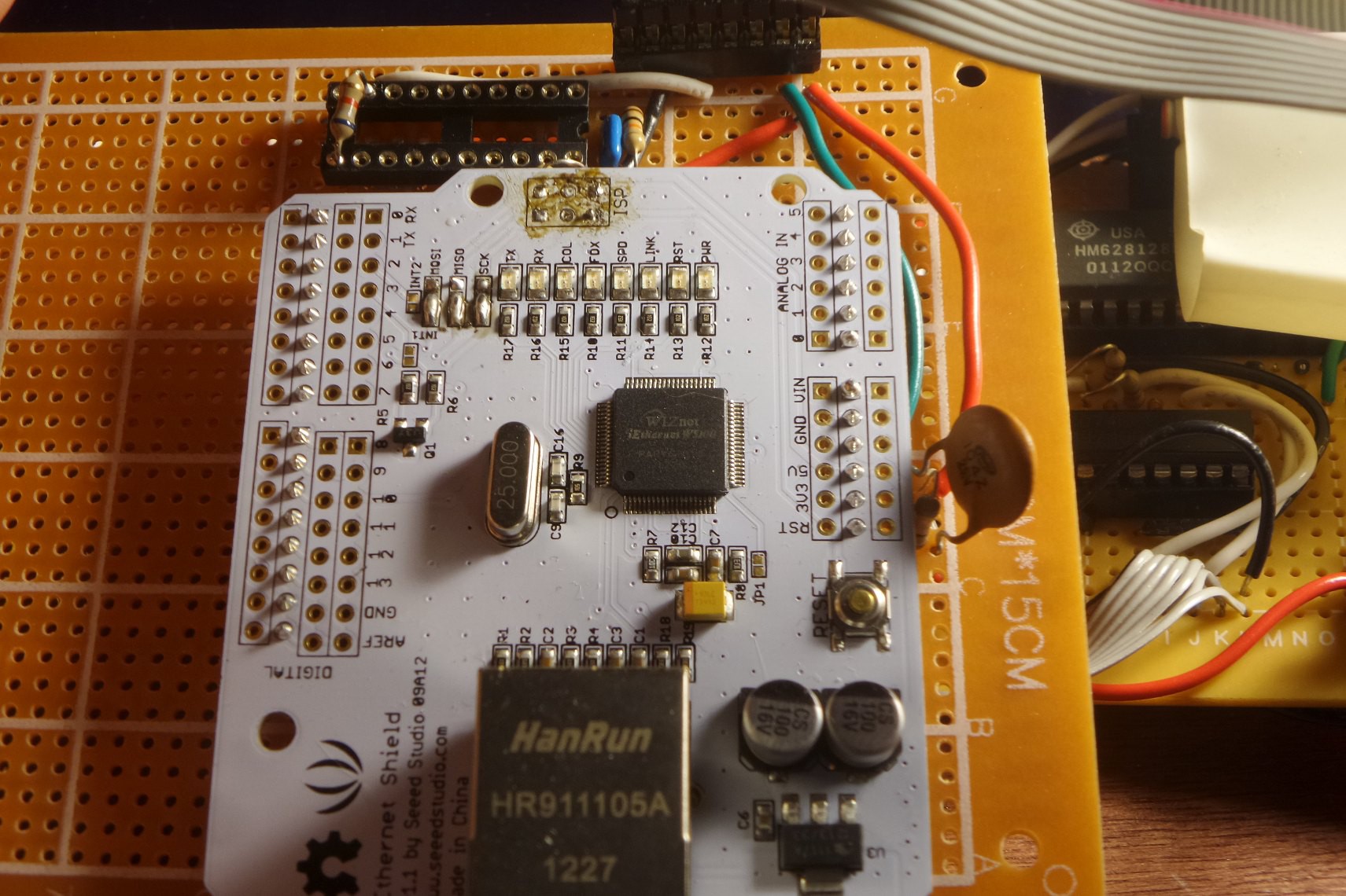
    Note, a homemade board is actually what made removing this socket easy: This board was intentionally designed so that all IC pins connected to the circuit ONLY on the bottom layer, because you don't have plated-thru holes, and the tops of sockets are inaccessible. Also, because there's no plated thru holes, the pin can't stick to the inside of the hold. If you use a solder sucker, it all comes out super clean and super easy. Of course a professionally made board with plated thru holes wouldn't have had shorted traces!

  • Been a while

    Mars09/26/2016 at 01:56 0 comments

    I had gotten super-busy with other things, and this project got shelved... I have a renewed interest in it since visiting the Vintage Computer Festival. I have create a to-do list to once the for all finish the project:

    1. Remove ethernet board. It was exciting to get ethernet added, but was premature and I don't like the way it is interfaced. The extra wiring also makes for a lot of noice on the bus.
    2. Finalize a base software image. The code I have on github is old, basically just tests the hardware. I want to at least have a base image (.hex) file that brings up all the hardware, and dumps the user in an interpreter environment.
    3. Filesystem: I have a driver that allows reading and writing of blocks on an SD card, and I have a simple block allocation/delteion/freelist scheme. A file is a linked list of disk blocks. If you allocate a block, you can chain many blocks off of it, and if you know the starting block number of a file, you can read the whole file. I considered FAT, but FAT has 4k clusters, and I'd rather work with 1 disk block at a time (512 bytes). Also, the fun of the project is building it yourself. A directory of files will likely be a regular file that just happens to have a list of files in it and their starting block numbers.
    4. Hardware rebuild: The physical hardware is a mess. It works. I will probably uncover problems as the software develops. I would like to buffer-isolate the external ram address bus from the spi bus as best as possible. Right now just too much happening directly off of PORTB. MISO definately needs really special handing, as it needs to accept: input logic from 3.3 devices, needs to be able to output 5v logic to ram addresses.
    5. re-add ethernet

    I have also considered adding a attiny84 or atmega328 to the project as a coprocessor to handle the sound, keyboard, disk, ethernet (its a "southbridge"), but someday there might be a CAT-644 R2.0.

  • Messy Ethernet Board

    Mars06/04/2015 at 05:05 0 comments

    Someone from Wiznet contacted me and wanted to see how I was using the Wiznet W5100 in this project. Here's a look at the ethernet interface. I am using the Seeed Studio Ethernet Shield, version 1.1 This version has since been discontinued by the manufacturer. There are a couple small modifications:

    1. The ISP header has been desoldered. It was in the way.

    2. The board has been solderd to a piece of perfboard with header pins. I wanted any modifications to this board to be as nondestructive as possible. I could still take this board off and put it on a real Arduino, if I wanted to.

    3. This board was intended for use on an Arduino, which already has reset pulled up to 5v. I added a 5v pullup resistor. The W5100 chip did not like being reset 'too fast', so a .1uf capacitor in parallel with the pullup makes the reset signal rise slow enough that the Wiznet sees a reset.

    4. On the top of the photo, you can see where I tried to buffer the output of the MISO line with an old 74244 tri-state buffer and failed horribly. The resistor is a cheap hack, which I covered in a previous post.


  • Software Update

    Mars05/18/2015 at 03:16 0 comments

    Now that I can communicate with both the SD card, and the ethernet (Wiznet) interface without interference from each other, I need to return to a key part of the system: The software. I have the following implemented already, with the intention of building it into more of an OS than just a library of random utilities.

    (virtual) memory:

    I've implemented a simple malloc replacement. The reasons I am not using the built-in libc malloc are 1) I want to write an allocator because I've never done so, and 2) I plan to do some unusual things that regular malloc will not support. Namely, I want to make use of handles. I already have simple malloc and free working, the next thing is to work on is dismiss and summon:

    handle dismiss(void*) : Given a pointer to a block, returns a handle to that block. The pointer from this point forward is considered invalid. The pointer input must be at the start of a block originally returned by malloc. (You can't just dismiss part of an array or struct, only the whole thing.)

    void* summon(handle) : Given a handle, returns a pointer containing the data that was saved in the handle. The pointer returned may be different than the original one passed in to dismiss.

    The idea here is that such a small heap may easily become fragmented. Large data structures, like trees, linked lists, etc, may refer to their members through the use of handles instead of pointers. Traversing a linked list will always 'summon' the next element, and 'dismiss' the previous element. What is the point of this? Summon and dismiss track what objects are currently in use, and provides a way to safely move objects not in use. The heap may be de-fragmented. Objects on the heap may even be moved out of internal AVR ram and into unused parts of the external (video) RAM, OR even swapped to disk. Poor man's virtual memory. The goal is a C program won't care where a summoned struct is coming from.

    scheduler:

    I've been running (in simavr, not on the actual Cat-644) a simple round-robin cooperative multitasking scheduler. I

    filesystem:

    read/write sd card blocks (raw)

    each block has a checksum, multiple blocks can be chained to create longer files

    unimplemented:

    delete (once a block is used, there's no recycling (yet). Remember filling 1GB from this machine will take forever. I have a while to deal with it.)

    directories: To read previously stored data, you need to know the block number to start reading from. This is exceedingly primitive. Plans are to put a directory file on 'block 1'.

    device abstractions:

    I have created 'block device' and 'character device' abstractions. Note, the definitions I'm using here are not quite how we would define them in LInux:

    generic device: Only supported call is 'ioctl'.

    character device: Can read/write 1 byte at a time (getc, putc), and has a test to tell if a character is ready (kbhit). Implemented block devices: ps2key (input only), serial (both), vgaconsole (output only), file (as on disk). Also has ioctl. For serial ports, IOCTL_SETBAUD, and for files, IOCTL_SEEK.

    block device: Can read/write 1 block at a time. All blocks are the same size (SD card is 512 bytes), and addresses are block numbers. THe only supported calls are ioctl, readblock, and writeblock.

    I have plans to let files and other char devices read and write more than 1 byte at a time, but I'll get to that as a lower priority.

    graphics:

    implemented: drawdot, drawchar, drawsprite, clear screen, flip video page

View all 18 project logs

Enjoy this project?

Share

Discussions

Vitaly Rudik wrote 02/18/2020 at 09:52 point

You can also try to overclock the MCU to 25MHz to have true VGA pixel clock. Perhaps you have seen similar project UzeBox http://belogic.com/uzebox/hardware.htm where ATMega644 works at 28 Mhz.

  Are you sure? yes | no

Vitaly Rudik wrote 02/18/2020 at 09:40 point

Hi Mark!

It is cool project! I looked at the schematics and noticed that you use only 6 pins for output to display. Why not add a couple of resistors to have 4 times more colors in 3R3G2B mode?

  Are you sure? yes | no

Alexander wrote 03/23/2019 at 00:10 point

Interesting choice of the ATmega644 -- did you choose a micro so you didn't have to bother using an external IO chip? I can definitely understand not wanting to deal with that.

Awesome work, very interesting!

  Are you sure? yes | no

Mars wrote 03/27/2019 at 06:16 point

I went with the ATmega644 because there were already a couple examples online showing it generating a VGA video signal so I knew it was up to the task.  PIC was also considered, but not fast enough.  I could have gone a more traditional route and used a microprocessor, but then I would have to have a EEPROM, and now I need a parallel EEPROM programmer.  And there aren't any 'fast' standalone 8-bit processors anymore that I know of; there are new Z80's with lots of built in stuff (so they are really microcontrollers again), and there is the WDC 14Mhz 6502... but its still not fast enough. There are also fast versions of the 8051, but that's back to a microcontroller.

  Are you sure? yes | no

Adam Fabio wrote 09/26/2016 at 04:20 point

Hey [Mark] You're a featured project on the Hackaday front page! Congrats!

  Are you sure? yes | no

Mars wrote 09/27/2016 at 20:49 point

Thanks!  Wow, how did that happen?  I haven't work on this in about a year.  I've been wanting to, I guess I really have to now!  

  Are you sure? yes | no

Adam Fabio wrote 09/29/2016 at 23:59 point

The featured projects are hand picked from all the awesome projects on .io.  I can't wait to see more progress on this! 

  Are you sure? yes | no

mrevilwrench wrote 02/09/2016 at 08:27 point

I caught sight of a picture of this, and the first thing I thought was "Ohio Scientific Challenger 1P".  I mean, the dimensions are all wrong, but google a picture.  Then I read some, and looked at your pix; you took me back 40 years to breadboarding my first Z80 :)  If you want to use sockets to protect your pins, I think you'd like the machined-pin type.  They'll protect better, insert easier, and the pins won't move.  Rock on.

  Are you sure? yes | no

Hacker404 wrote 06/04/2015 at 05:03 point

Hi, I have two retro computer projects under way at the moment and I would like to use cheap PC (Desktop) keyboards. Can all USB keyboards work with a USB to PS2 adaptor? And is there any special considerations or do they work exactly the same way as a real PS2 keyboard would work? 

  Are you sure? yes | no

Mars wrote 06/04/2015 at 14:58 point

The vast majority of cheap USB keyboards will work just fine as a PS2.  If you have a bunch of keyboards lating around, I bet most or all will work.  Expensive gamer 'usb 2.0' keyboards will not work.  If in doubt, buy a keyboard that advertises ps2 compatibility as a feature, or one that comes with an adapter.  I don't know if ps2 support is 100%, but I didn't have to make any special modifications.

  Are you sure? yes | no

Hacker404 wrote 06/04/2015 at 20:58 point

Thanks. I have been collecting PS2 keyboards thinking that USB didn't work with PS2. Thanks again, Great help. 

  Are you sure? yes | no

Eric Hertz wrote 05/18/2015 at 01:34 point

Hey, great explanation in the details re: "Fast VM Interpreter"

That was my first question, regarding how to build an AVR-Based computer... excellent explanation. Thanks!

  Are you sure? yes | no

daniel wrote 05/06/2015 at 06:35 point

hi

My name is Daniel, at WIZnet in Korea.  
We have been searching some application references in which WIZnet solution is applied, and found your project  using WZnet's W5100. Your development looks very cool & smart. 


Recently we opened WIZnet Museum (http://wiznetmuseum.com) site. This is a academic-purposed collection of open projects, tutorials, articles and etc from our global customers. 

If you are O.K. we would like to introduce your projects in here. Hopefully, you will allow this.

Hopefully, keep contacting us for the friendship.

Thank you very much

I will waiting for your reply.

  Are you sure? yes | no

hackaday wrote 02/08/2015 at 15:33 point

Idea for high-res video:

https://sites.google.com/site/guenterbartsch/home/atmega1284p-composite-video

ATMEGA1284p has enough internal RAM to handle 512x220, for an AppleII-ish 80x24 monochrome bitmapped display and 2KB RAM left over for other stuff.

  Are you sure? yes | no

Mars wrote 12/05/2015 at 20:59 point

Thanks!  Yes, its been a long time since I've checked my messages here.  I have thought about upgrading to the 1284... it will give me much more ram.  You might have missed it, but one of my previous project logs did manage to just eek out 512x240 video on the 644.  It used 120 of the 128k external ram, and took 95% of the CPU.  Whenever I have time to work on this again, I would like to add a monochrome mode that uses less memory.

  Are you sure? yes | no

Similar Projects

Does this project spark your interest?

Become a member to follow this project and never miss any updates