Norbert Fekete
-
Editing the editor
09/17/2017 at 15:44 • 0 commentsIt has been a long "vacation" break. Well, if some can call a full-time job like that. :)
At the point of the merge of the editor branch, I've decided to call it "alpha v0.1". Sooo.. what's up next?
Alpha v0.2 goals:
- Core editor features and cleanup: add new core, add/remove packages, edit peripherals, save/load the core.
- Module editor features and cleanup: add/remove/modify front and back images, edit peripherals, save/load module.
This doesn't sound much, but with these the main tool will be more usable.
With this "tool inside the tool" it will be much more easy to add content. And with content, this concept can become really usable.
I will try to make it as easy as possible for everyone to contribute through the editors.
-
Editor merged into master branch
07/05/2017 at 16:25 • 0 commentsFinally an update on the "public webpage"
After a long time, working on a separate branch I've finally decided that it is time for a merge.
Of course this is full of old and new bugs, looks a bit ugly, but some new features are also there.
New stuff:
- Horizontal pin arrays: While still buggy, it now supports horizontally aligned pin arrays, and the labels can be on upper or lower side.
- Refactored the JSON files containing core and module info: This is not visible, but accessing core and core packaging information can be made visible on the webpage someday using the current data file structure.
- Editor Mode: For now just existing modules can be edited, in a limited way. Open a module in normal mode, then click "Editor Mode" and it can be changed.
Features still on their way:
- MCU editing: During module editor testing I still had to edit the core JSON files manually. Painful thing to do, it will have its own editor.
- New core/module: For now creating new stuff needs heavy manual file editing.
- Edit peripherals: Add peripheral editing to both MCU and module.
- And lots more, primarily for the normal usage: Peripherals need to be checked for collisions, invalid pin usage. Show visually on the module image the input/output/pwm. Include also image from backside, and have a "flip" button. Maybe include quick link to datasheets and board schematics.
And many more I forgot to mention here, plus heavy bugfixing.
For now, vacation awaits! :)
-
Editor still on its way
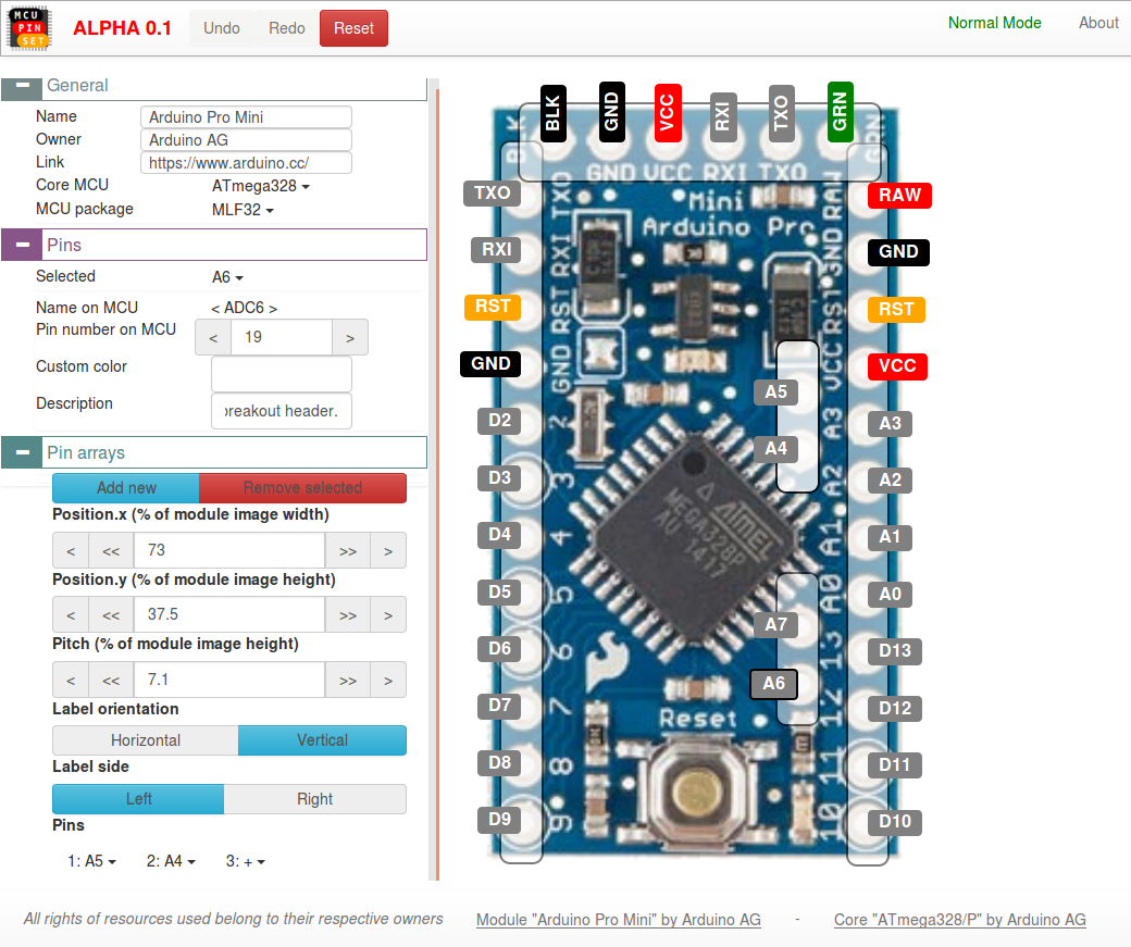
06/23/2017 at 09:28 • 0 commentsAs I wrote in the previous update, the main development focus is now on the editor, and it kind of looks like this now:
![]()
Finally have the really basic editing tools in position, and it looks like something.
Features for now:
- Only module editing yet.
- General info setting: More-or-less functional.
- Pin setting: With a bit of documentation reading it can be set.
- Pin arrays: Add/remove, drag, set position and pitch with precision, horizontal/vertical, label orientation, and set the list of used pins.
- Undo/redo/reset: Very buggy, kind of works. Reset is a hard reset to base. Current state is stored locally, so after browser restart, editing can be continued.
Problems and TODOs:
- LOTS of bugs everywhere.
- General info should have some description included maybe.
- Core cannot be set, the drop-downs do nothing. Changing core and/or package is pretty serious thing to do in the middle of editing. Should alert that existing pins and arrays will be for example erased.
- Pins on the board cannot be added, removed, or their names changed. :)
- Also if a pin is not routed from the MCU then the "Pin number on MCU" is kind of weird to have. Need to add a "Routed from MCU" checkbox.
- Pin array dragging with mouse is ridiculous for now. Working on it.
- Drop-down selectors bring up a menu under the scrollable space, very annoying... Trying to find solution.
- The whole section for peripheral notes is missing, need to implement it.
- Select the module which should be edited, and have an "add new module" menupoint, with a quick-setup (set module name, image, core and package) for example.
- Module image selection should be added. Would be very hard to add new modules without setting an image for them. :D
- Include save and load feature for God's sake! How could anyone contribute if the edit can't be saved?
- And of course implement MCU-level editing, so the tool can be fully universal, and include many MCUs and modules.
And after these, I can get back to the REAL tool, because this is "just" the editor mode!
-
Editor is on its way
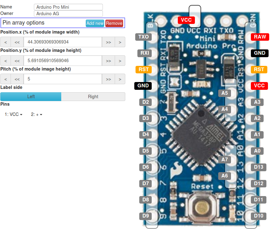
05/31/2017 at 10:58 • 0 commentsIt may look like I've been doing nothing with the MCU pin setup webpage in the last few weeks:
Well, it's because I haven't. :)
What I've actually been doing is on the "editor" branch, which can be found here:
https://github.com/Hubberthus/hubberthus.github.io/tree/editor
With the editor anyone will be able to easily modify and/or add cores/modules to the MCU pin setup tool.
It can be tested out by getting the source and double-clicking on the "index.html", no webserver is needed actually for the page to run, just a good browser.![]()
Anyway, the "editor" branch is unstable and for now is nearly completely useless. But I'm working on it, and when it becomes usable, I'll merge it into the so-to-say release branch.
Features expected to be done:
- MCU core add/modify:
- Basic and detailed information
- Packaging and additional info if any (ground pad, unrouted pins, etc.)
- Pins with detailed information (input/output, PWM, internal pull resistors, etc.).
- Peripherals with basic information, pin usage, and additional options (clock source, speed, mode, etc.)
- Module add/modify:
- Basic and detailed information
- Images from front and back sides of the module
- WYSIWYG pin layout, naming and additional information for the board (onboard resistor, LED, etc.)
- Additional information for peripherals affected by the board (built-in, unrouted, etc)
- Load/save edits made
- Update main page by providing the custom edits to the developers (most probably via the github. Pull-request, or issue with the file attached)
- MCU core add/modify:
-
Focus shift: Create an editor
05/06/2017 at 20:01 • 0 commentsThere hasn't been very visible updates for the page, and my focus on code generation kind of got me tangled in.
So let's do something that matters!
And with this statement in mind, I'll hide away the code generation funcionality (at least I won't have to write it again when needed)The focus will go to the editor page so anybody can simply edit/add cores, pin information, peripheral information, module information. And all this on a nice user-friendly page.
Then, all updates and new additions will be welcome, this tool can only be something useful if many cores and modules are in.
Next steps then:
- Create the editing page
- Come up with a good idea for "editing project" saving
- Main page updates:
- Pins should have arrows showing direction, and possibly indicate somehow interrupts and pwm
- Backs side of modules should also be added
- Cores should also be browsable, without any board
-
Concentrate on Arduino and HW test idea
04/28/2017 at 15:02 • 0 commentsI'm currently concentrating on full functionalty for the Arduino Pro Mini, which includes lots of documentation reading and head scratching.
The JSON file formats describing the MCU, peripherals and module should not be too complicated, but also robust to allow lots of customization. This is applicable also for code templates: don't make them a huge mess, but they need to handle everything.
So this task also covers the sanity check implementation, and as I see dependencies, effects on other peripherals, info/warning/error messages.
Lots and lots of stuff that need serious consideration.
This is why I did not start the JSON and code template documentation yet. After getting the Arduino in shape, it can be a good base for documenting the "rule machinery".
Of course I need to do tests with the module to see if the generated code works, and I thought of a funny small "project" for which I will also create a tutorial. Kind of show the potential in this.
The project-in-this-project for my Arduino will be a module talking to itself via SPI.
As I've learned from the docs, the USART can be used as a master SPI. So by making the standard SPI on the device as a slave, these two can talk to each other. The whole process can be monitored through a SW serial. It will send random bytes from master to slave, verify it, and answer with another set of random bytes, also verified.
It will need some setup and interrupt handling. I hope that using the MCU pin setup tool, it will be a lot easier than doing all the setup by hand.
-
Code template not regex anymore!
04/20/2017 at 13:11 • 0 commentsFirst things first, I've done the brief introductory video:
And for this, I've made several modifications to the page.
A big modification was for the code generator, which simply used a silly-looking regular expression. That temporary solution is now replaced with a template library. More advanced code generation can be done now, the real fun begins!
Next steps
- Start writing documentation for the JSON file formats. These store the MCU core, peripheral and module information in a human-readable style.
The documentation will be available on Github Wiki of the page. - Add sanity checks so the tool can give warnings and errors instantly. Maybe also information like: "You may need external pull-up resistors for the I2C pins"
- Start making an editor page where everything can be edited visually, instead of writing the JSON manually. Will speed things up. As it is a big sub-project, it won't be available in the near future.
- Concentrate on the Arduino Pro Mini's all features, try to make at least the Arduino code flavor fully working, so it could be used as a base for others.
- Think about some small project (ore more than one) which could be done with this tool. Example use-cases can show its potential.
- Start writing documentation for the JSON file formats. These store the MCU core, peripheral and module information in a human-readable style.
-
First use of generated code
04/07/2017 at 13:58 • 0 commentsHere is the first cross-MCU code which was used as a test.
A simple blink, which runs on a FreeRTOS task.
#include "mps.h" void TaskBlink(void *pvParams) { for (;;) { digitalWrite(LED_BUILTIN, HIGH); Serial.println("LED on"); delay(1000); digitalWrite(LED_BUILTIN, LOW); Serial.println("LED off"); delay(1000); } } void setup() { initializeMPS(); pinMode(LED_BUILTIN, OUTPUT); task(TaskBlink); } void loop() {}- Includes the MCU pin setup tool's generated main header. (Which includes all necessary headers as well)
- Defines the task which blinks the led in an infinite loop, and prints out text on Serial.
- Calls the MCU pin setup initialization function which does the initial setup. If our case for example "Serial.begin()" is called inside, if the UART was enabled in the tool.
- Sets the builtin LED pin to output.
- Starts the task, and does nothing in the idle loop.
For Arduino, the Arduino-FreeRTOS library is needed, can be installed in Arduino IDE's Library Manager.
For ESP32, the ESP-IDF needs to be set up, leave the "main.c" totally empty, and put this code into e.g.: "app.cpp". I know it is a bad workaround, will think about it more.
In "make menuconfig", the idle loop for FreeRTOS must be enabled! It uses that for the main loop. It is ugly too, I know.
But with this, the code is nice and readable, and is the same for Arduino Pro Mini and ESP32.
Next step, do a video tutorial about this.
-
Code generation progress
04/06/2017 at 13:50 • 0 commentsNew board added
To have another MCU, I've added Arduino Pro Mini board with ATmega328. It is available now in the "Module" drop-down menu.
Of course it's not complete and has flaws. Bugfixes will be done, this is still just at a proof-of-concept level.
User can now select between "pin layout" and "generated code" views
The layout view is the default which was available before.
The code view allows the user to see what will the generated code exactly be. Of course it is not editable, but is instantly updated if settings are modified.
For now nearly nothing is implemented, and it has only one code flavour: Arduino-FreeRTOS. This decision was made to test if I can make an application code which runs a RTOS "blink" task, and this very same code could run on an ATmega328 and ESP32. It was a success, however needed a bit of thinking, and handling colliding things, like minimal stack size for different MCUs. (Made the ESP32 go into reset-loop because of too small stack)
The generated code has an Arduino flavour, so those who are used to the Arduino coding style can use familiar methods on other MCUs as well, with RTOS additions. The intention is not to replace Arduino, because other MCUs have virtual Arduino core. Of course "vanilla Arduino" flavour will be added as well.
For now I would like this to act also as an educational tool to easily understand and start coding an RTOS application.
A "Download mps.zip" button was also added, in order to quickly download the whole generated code.
Next steps
- I intend to make an introductory video with the stuff already done. It's simpler to show what my intention is.
- I've found a nice UML to code generator tool, will try it out, and if works well, it could be used together with my tool, simplifying the whole application creation even more. I believe that with visual tools, efficiency of education can be boosted.
- I'll have access to a Maple Mini, I will add also that one, so I'll have also an ARM based MCU in the tool.
- Define a more complex project, with I2C, SPI, ADC, inputs/outputs, several different tasks, event queues, and of course do it using the MCU pin setup, and optionally an UML to application code generator tool. It does not need to be fully cross-MCU, 8-bit and 32-bit cores are really different.
-
Automatic code generation
03/28/2017 at 14:45 • 0 commentsI've put the initial code generation commit into my website: https://hubberthus.github.io/
It creates a basic header which can be downloaded as a zip file. Has no functionality in it yet.
But if you turn on/off the "ADC", it will include/exclude code, so preprocessing via JavaScript can be done.
I've been thinking lately a lot about the automatic code generator, which could be a powerful function of this tool.
If I think in FreeRTOS, then there's several MCUs I can use, it is available for:
- Arduino (even 16-bit with ones)
- ARM-based MCUs, like STM32
- ESP8266 and ESP32
- and so on, and so on...
There is a trend to become Arduino-compatible because of its simplicity and number of libraries it offers. Virtual cores are being developed for it so anyone familiar with Arduino can do a simple jump-start.
Something similar could be achieved for FreeRTOS.
Why FreeRTOS?
It provides a different approach than the standard "main loop+interrupts". And can also be made easy using UML modeling tools supporting FreeRTOS. Imagine your kid just drawing the threads and state-machines, then simply generate the application code from it. Could be a great way of teaching multi-threaded real-time OS approaches to problems.
Adding the MCU pin setup tool the virtual layer code can also be generated automatically, based on a very visual setup.
If this tool could create a generic C header file as a basic interface for all kinds of MCUs and boards, and C sources would be based on the specific MCU with the specific setup done.
A Makefile then could be used to select from targets, like "make arduino2560", "make esp32" or something like that.
Now, this tool can be used to create the pin layout, and turn on/off and setup peripherals. Also, different MCUs can have specific peripherals available.
This difference can be however handled by giving back an error code (or throwing an exception in case it would be in C++) if the code tries to access unavailable peripherals. For basic features like UART, I2C, SPI... it should not be a problem to have cross-compatibility. Other unique features should be handled by the application if it wants to be cross-MCU-compatible.
As test I will try to make something run on an Arduino, an ESP32, and also an STM32. Wish me luck..
MCU pin setup
Visual pin layout setup tool for development boards with an editor mode for community involvement