The Loxone is an amazing peace of hardware. It works good and I am very satisfied with it. But the output relay (click clack) are not from this century anymore, so I decided to change the outputs of my Loxone. I bought some cheap SSR relays on aliexpress (https://www.aliexpress.com/item/FREE-SHIPPING-S216S02-S216S02F-S216-TO3P-4-5PCS/32802165635.html ). They work fantastic. Do you also want SSR relay on your board. These are the steps how to do it:
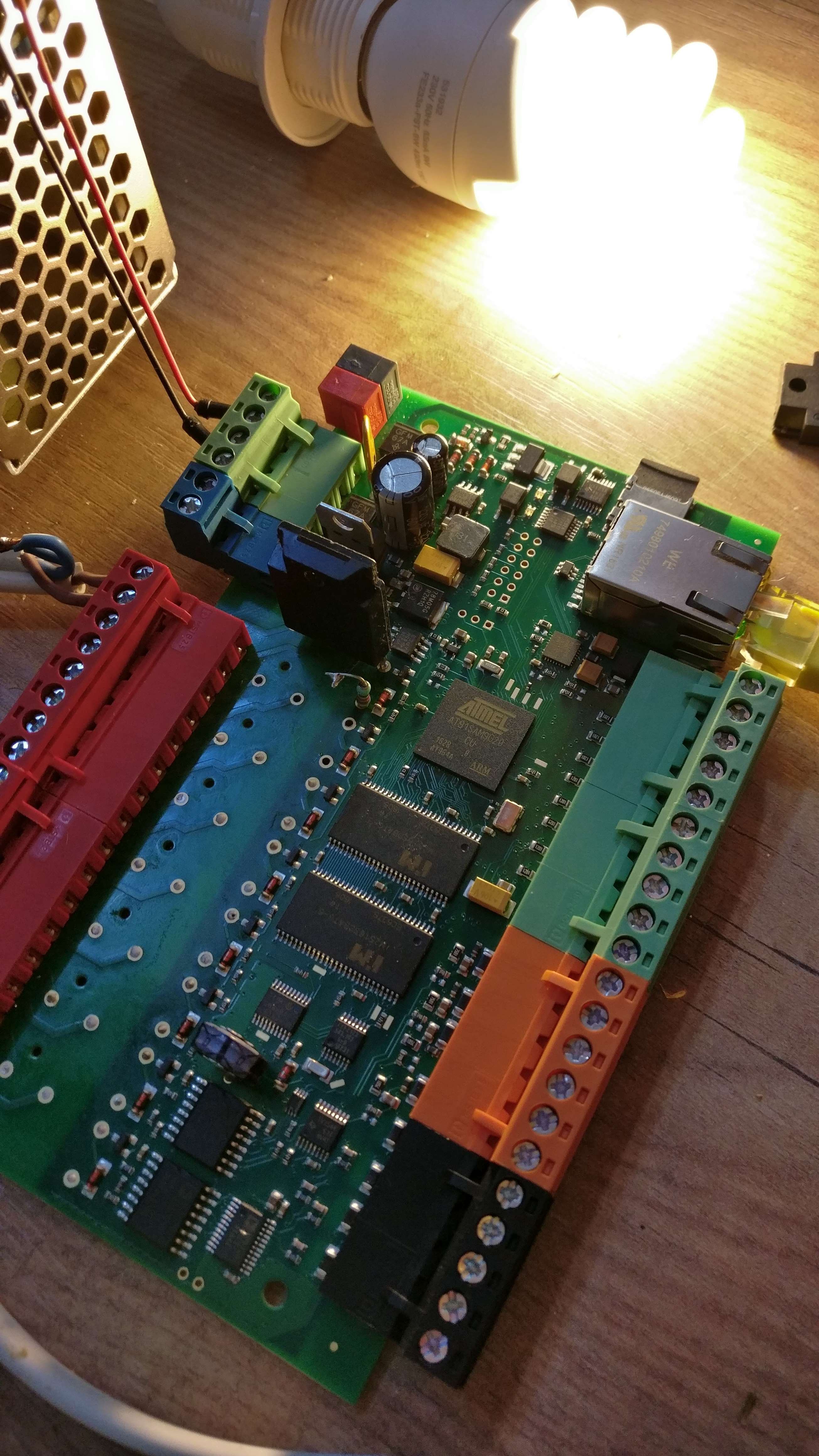
* open your Loxone. Carefully put a small flat screwdriver between the plastic tabs and pop it open.
* Look for the white relay. Carefully put some leaded tin on the bottom side of the PCB where the relay is soldered. Desolder it by using soldering wick, an desolder station or carefully heat up the whole footprint of the relay with a SMD hot air gun (please be careful with the last option, because it's a double sided board and you don't want to desolder other parts. This option is not recommended for beginners).
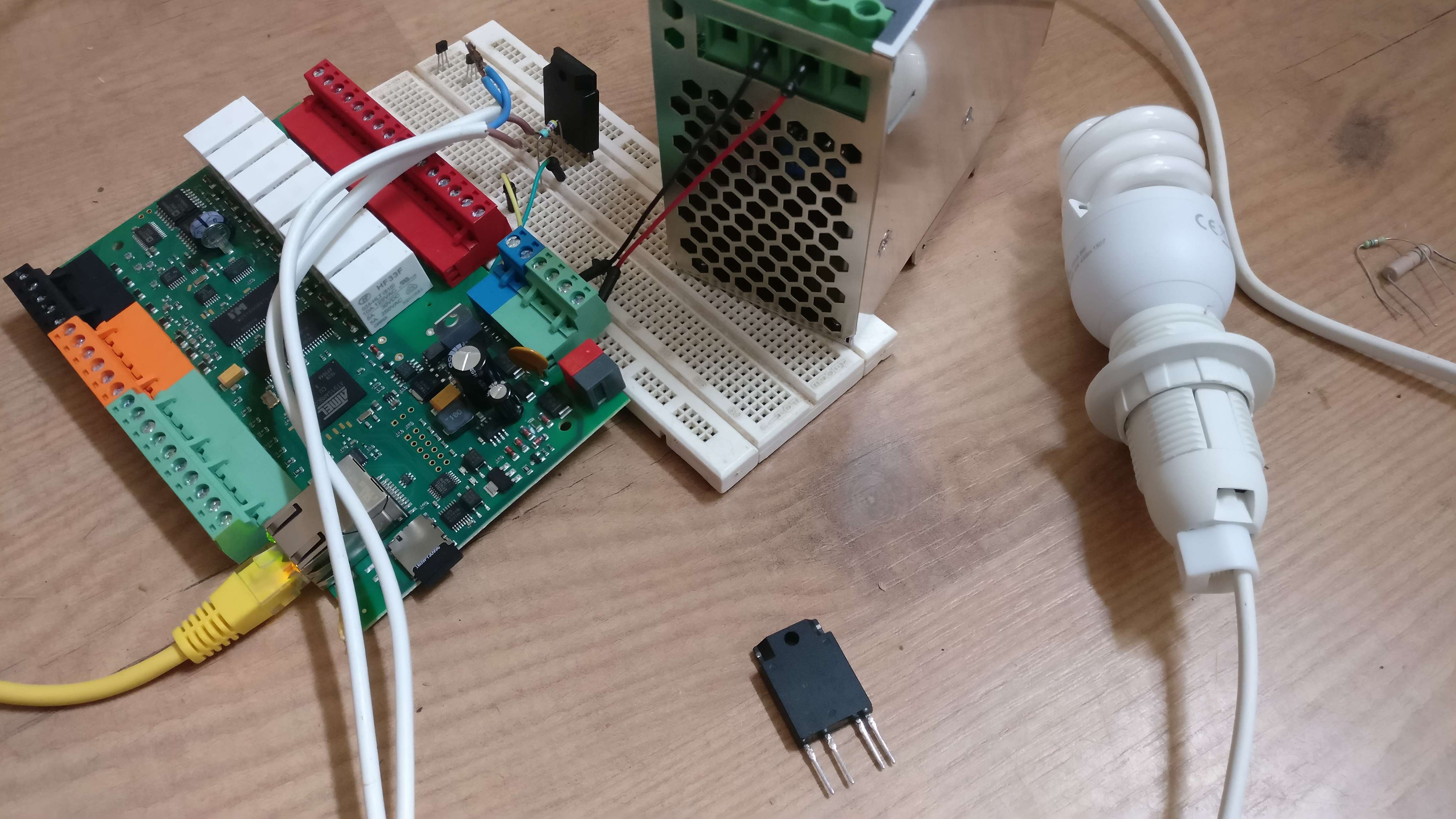
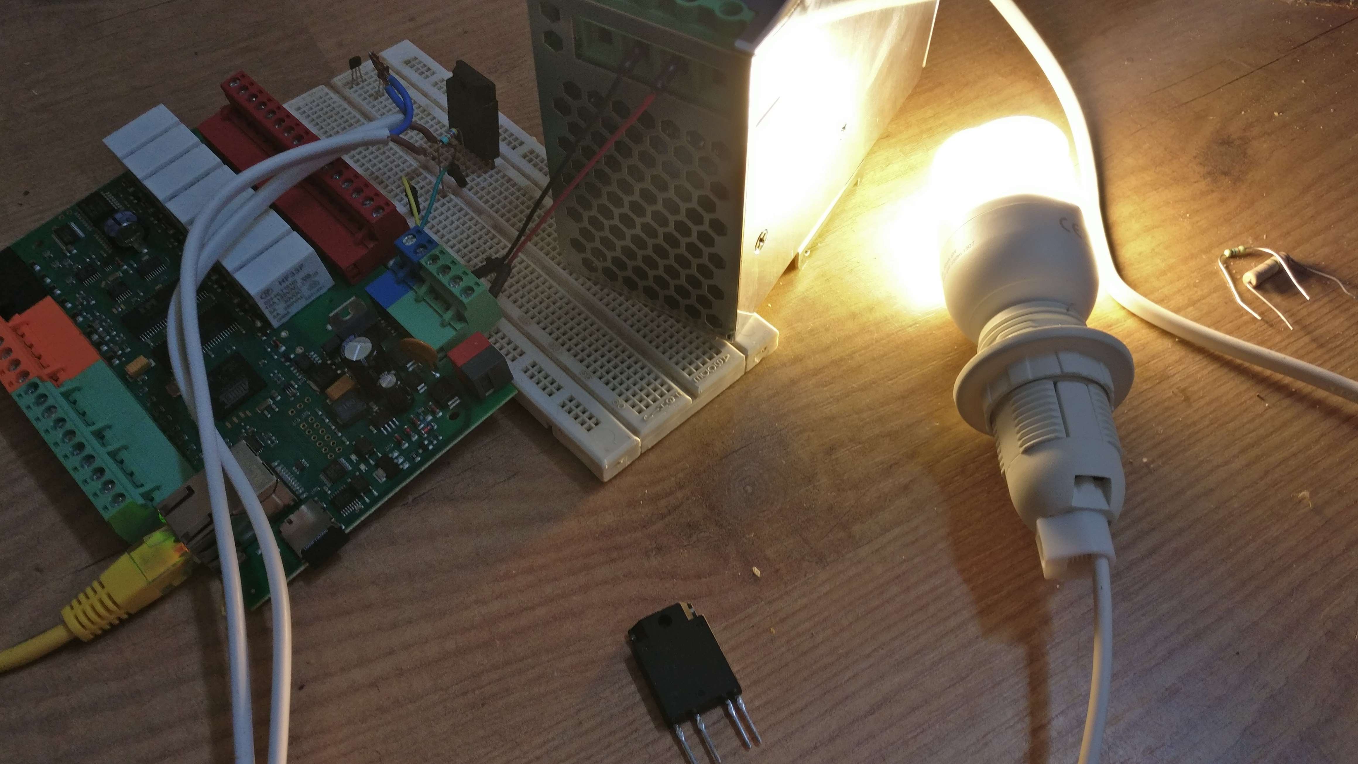
* When the relay is gone, now you need 3 part for each relay output: The solid state relay itself. A 1W 1500R resistor and a varistor. I use the S216S02 SSR, the 1k5 1W from farnell, ERZE08A511 - TVS Varistor Surge Absorber for each output. The 1k5 resistor limits the current (16mA for the LED input of the SSR) and the TVS protects the SSR against high voltages on the output (inductive load). The SSR outputs will be connected with the terminal block and the connections of the relay coil will be replaced by the 1k5 resisor in series with the SSR LED. So connect the + of the coil to one side of the 1k5 and the other side of the 1k5 will be connected to the + of the LED of the SSR. The - of the SSR LED will be connected to the other connection of the relay coil. Tuesday I will provide pictures. Put a varistor in parallel to the connections of the terminal block. This will protect the SSR. You can also add a resettable fuse if you want a 'perfect' ouput.
* Tuesday I will post my solder work and further instructions ;). The SSR will stay cool, so I probably don't need any heatsinks. The is 1 downside to the solid state relay... You can only use it for switching AC voltage and not little analog voltages or DC voltages. For debugging it is annoying that you lost your click signal to check if the relay in turning on or off. But this is why I want it in my house. No click sounds. The SSR is a semiconductor, so it should last much longer (if you use the varistor against high voltages). The SSR that I use here can also handle more current (16A max). To maximize the current up to 16A you have to put wires in parallel with the PCB connections from the SSR to the terminal block. The PCB lines are not that thick and can probably not handle 16A.
This is my test with the SSR. And yes, I know, the blue wire from the mains must be isolated with tape ;)
Disclaimer: Please only do this when you know what you are doing. I can not be held responsible for any damage caused by modifying the Loxone. You probably risk that you don't have any warranty on the product anymore. Making the wrong connections can harm the PCB and also yourself (output of the AC voltage of the SSR connected to the low voltage part of the Loxone).
See my other project page just for this modification of the Loxone.
Discussions
Become a Hackaday.io Member
Create an account to leave a comment. Already have an account? Log In.