I have ordered a housing on Aliexpress. The PCB will fit into this housing: https://www.aliexpress.com/item/6-pieces-a-lot-plastic-box-electronics-88-59-107mm-3-5-2-3-4-2inch/1625472251.html
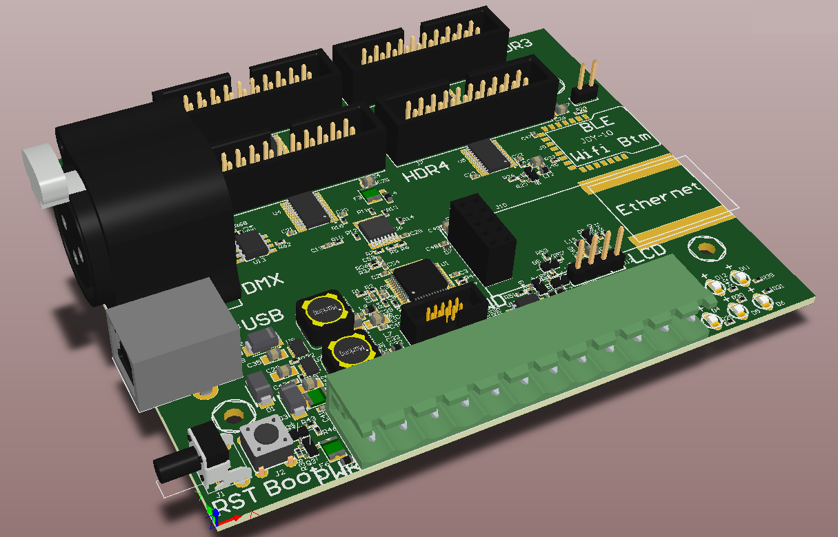
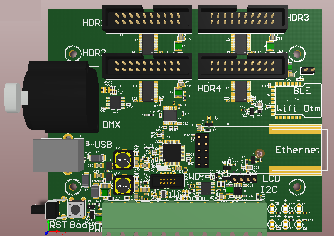
These are some pictures of the current PCB. Schematic have also changed a little bit (made it possible to have 3v3 and/or 5v IO ports). The size of the PCB will be 105mmx85mm. (4134mil x 3346mil). I did the most important job already. Placed the components in a logical way for easy routing. The Modbus and DMX512 will be a differential pair with a 120 Ohm impedance. The USB 90 Ohm of course. I will also tune the SPI (ethernet) and I2C.
I made also an very important update in the schematic to enable the SAM-BA bootloader. JTAG-SWD is also available on the PCB, but this is only for the experts. Normal users will reset the PCB with the bootloader button pressed and the will just have to program the Arduino bootloader into the board. Then you can program the board in Arduino. Is the board fails, you are able to restore the Arduino bootloader with the procedure mentioned before. You will always be able to restore the board software yourself.
The ethernet PCB will be mounted in a good way. The outside of the HanRun connector will be soldered onto the mainboard (see copper tracks around the word Ethermet). This will be a very solid construction. The green socket header below is : PWR, 1-wire, ModBus and external I2C. You can use the external I2C for external ADC readings, temperature sensors, light sensors, etc. After the board is finished I will give some suggestions to get you going.
I also will make a SSR board and opto coupler board (since the IO's are not protected well). This is not possible due to the flexible design. You can make each IO an input or output. The IO's will not be able to handle 24VDC, but with an external board you can use 24VDC logic levels. Now the IO's can handle 3v3 and 5vdc as mentioned before. I will make the LCD and LEDs on the top side of the housing. You can connect wires between the on board LEDs and LCD connection. LCD and LEDs are optional. Just what you want....
Discussions
Become a Hackaday.io Member
Create an account to leave a comment. Already have an account? Log In.