Close
0%
0%

Blinky, the Companion Robot

Blinky, a robot, lives with you, feeds itself and will--when asked--report that you have been seen moving around.

Similar projects worth following
Sometimes, you need to know if a person is up and about.

Blinky, powered by three thousand farad capacitors, "lives" in the house, roaming around. Blinky, when it sees you, "blinks" and "waves." Blinky, when queried through the internet, will respond "Yes, I've seen something moving around during the last few hours," or "looks pretty dead around here."

I learned a lot about power consumption, weight, the "uncanny valley," and useless features through work on "Mato." https://hackaday.io/project/10162-little-friend

I learned how to find a specific target (like a charging station) and how to stop and back out of a homing place through work on "Pretty Useless Machine." https://hackaday.io/project/14992-pretty-useless-machine

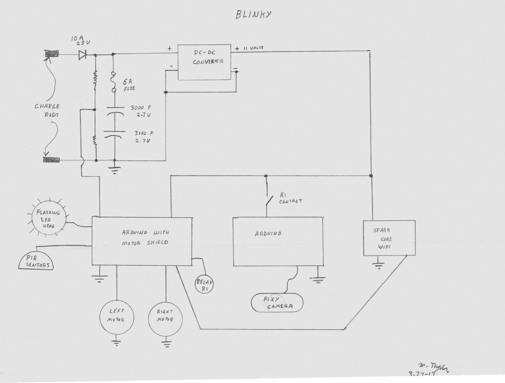
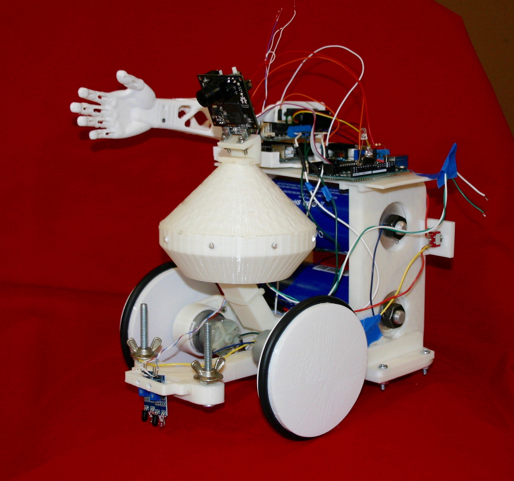
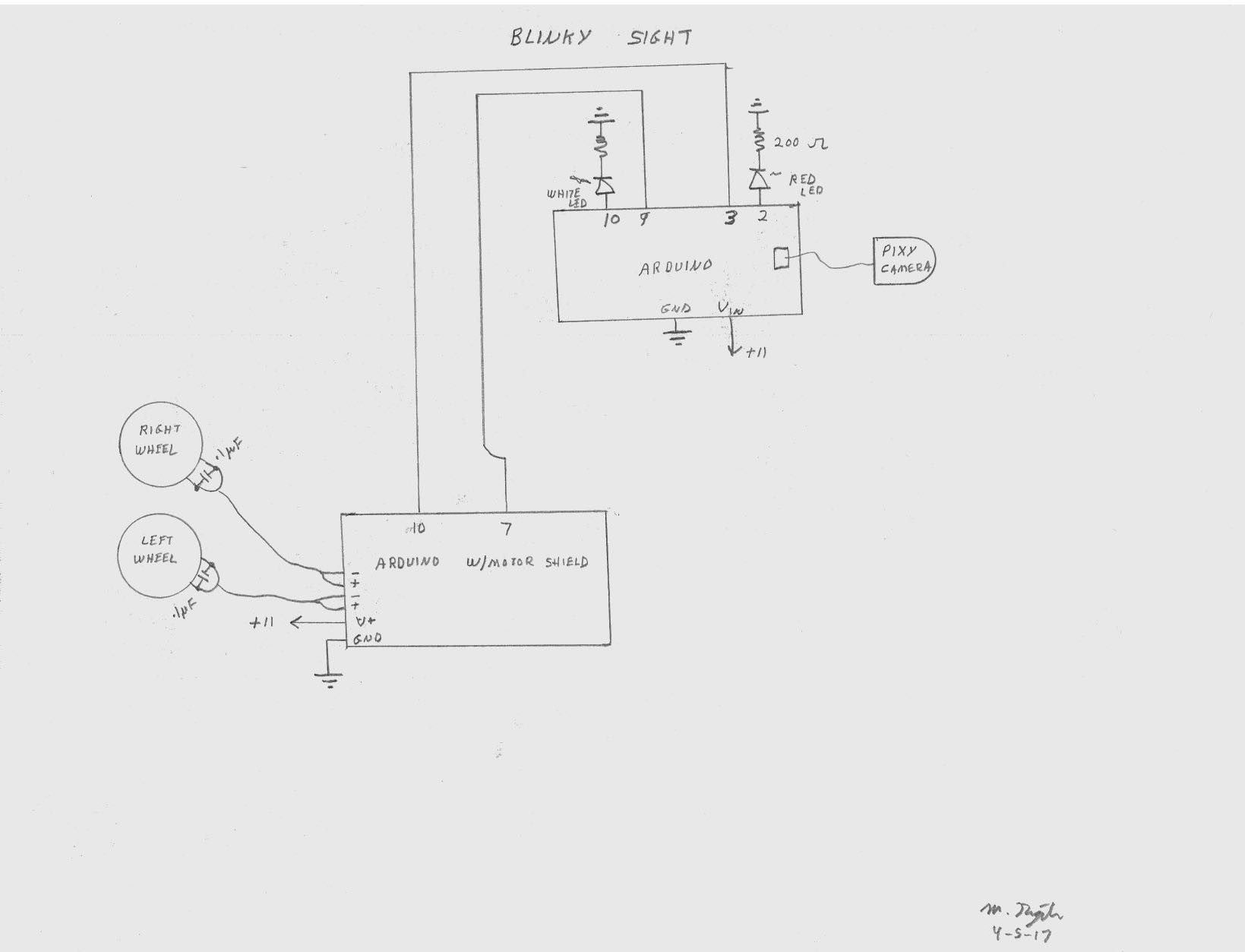
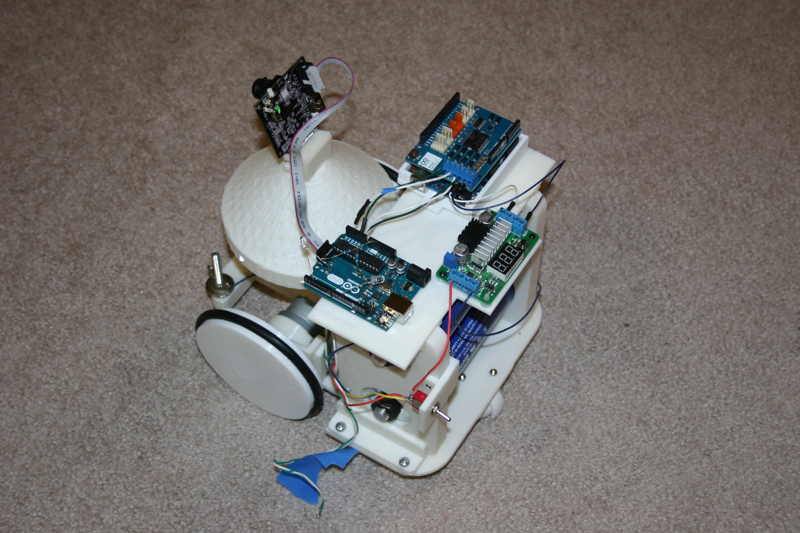
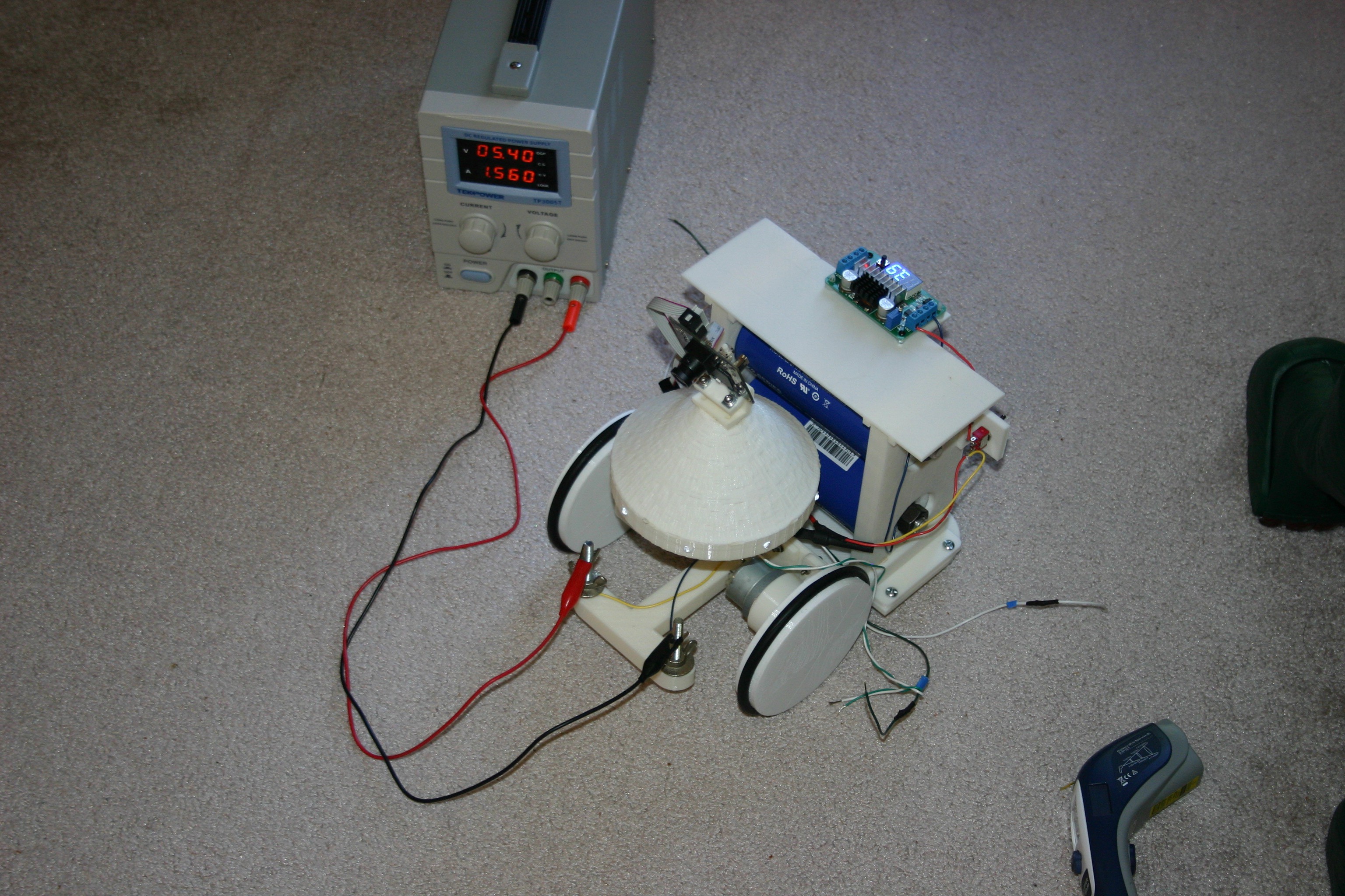
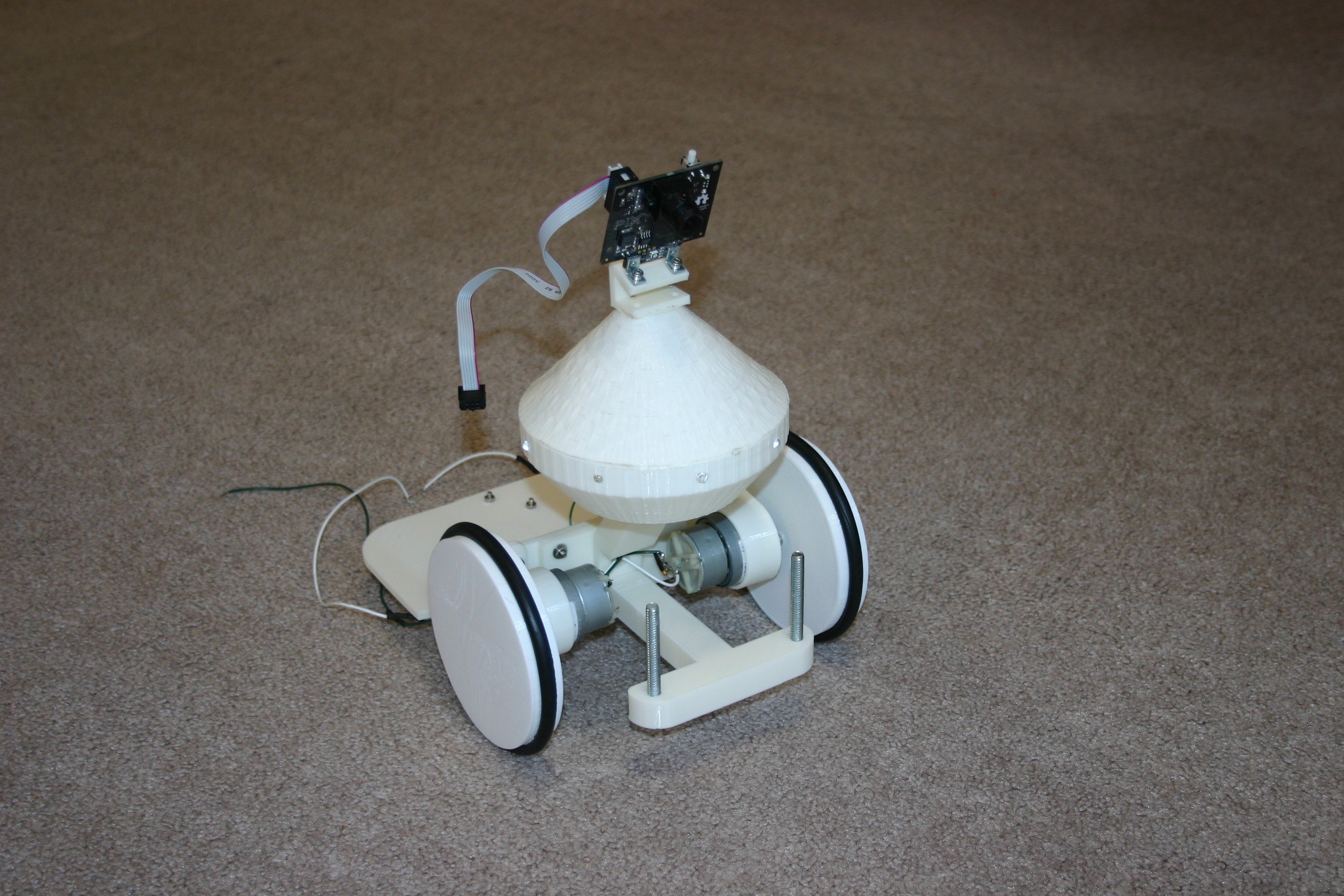
Below is an overall concept schematic of the electronics involved in Blinky. Blinky will wander about (changing course and retreating from obstacles) and frequently stop. While stopped, it will check the PIR sensors for movement and forward movement information to the Spark Core--from which it may be remotely retrieved. When the capacitor voltage reaches about 3.5 volts, Blinky will search for the charge station for a refuel. The charge station schematic and overview will be provided later.

Below is a video of Blinky moving toward a "target color" that will eventually be the charging station.

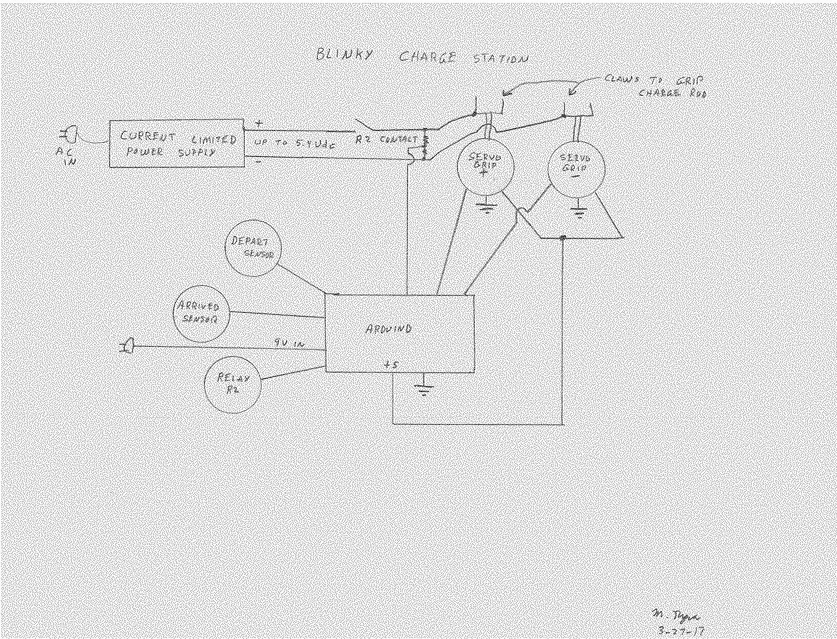
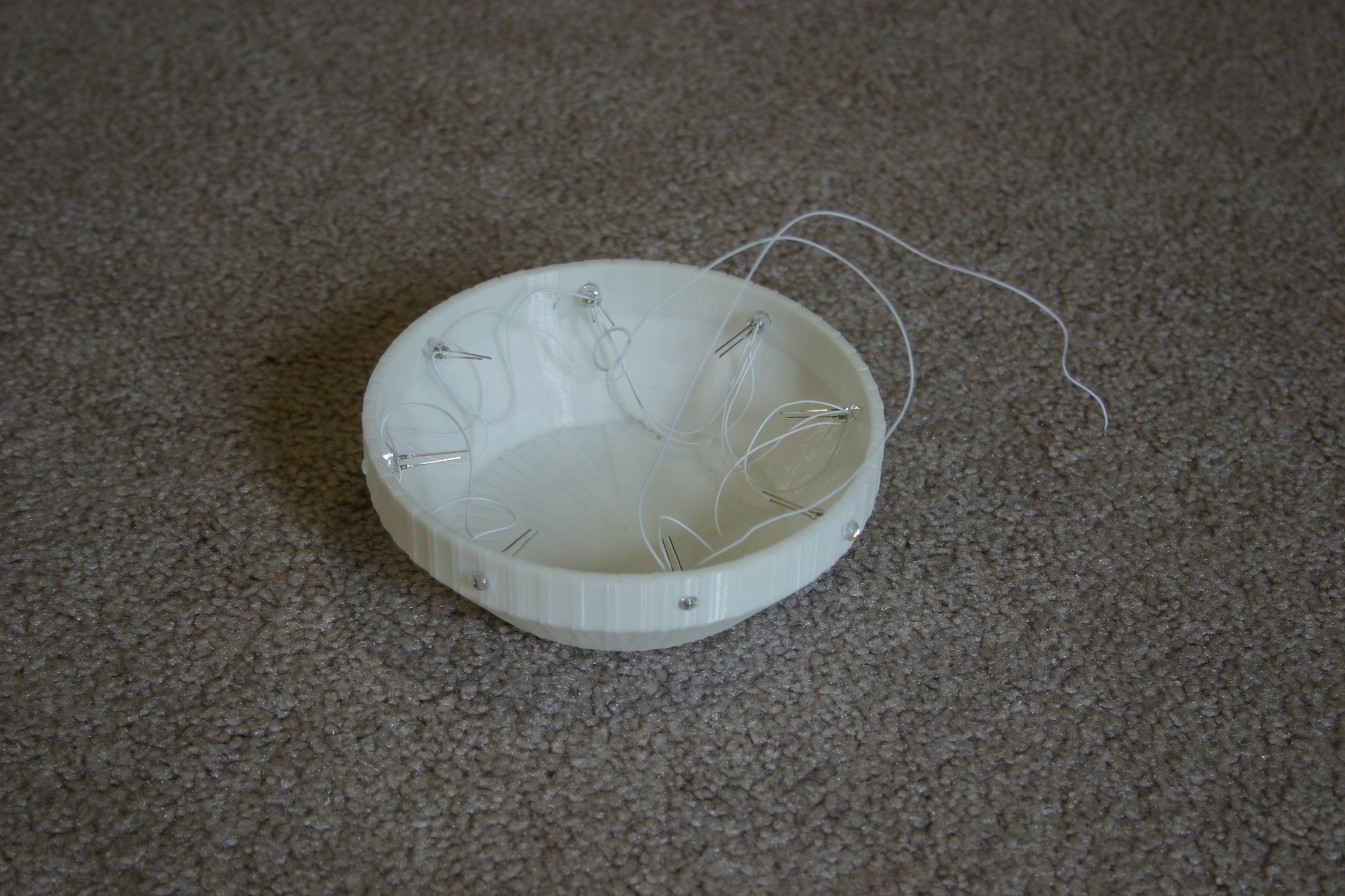
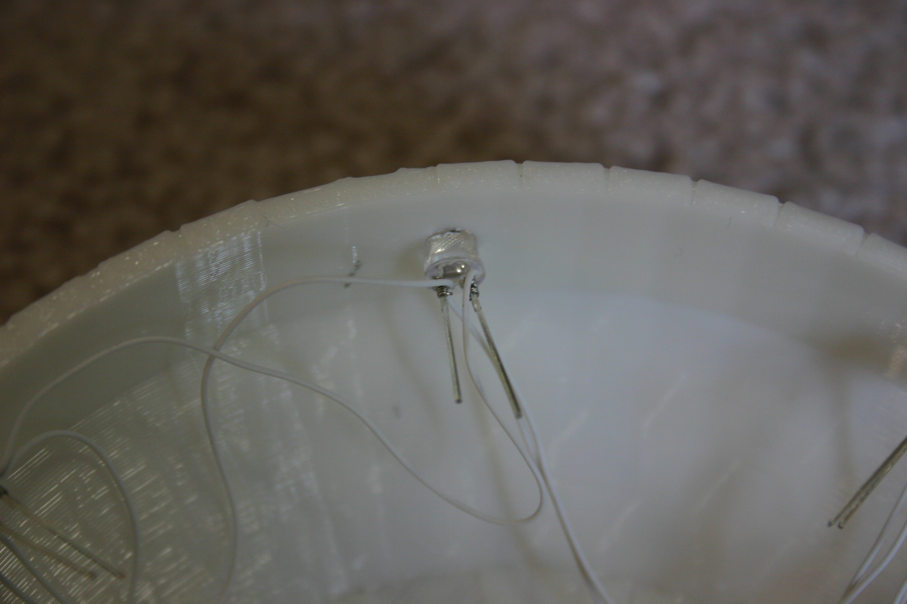
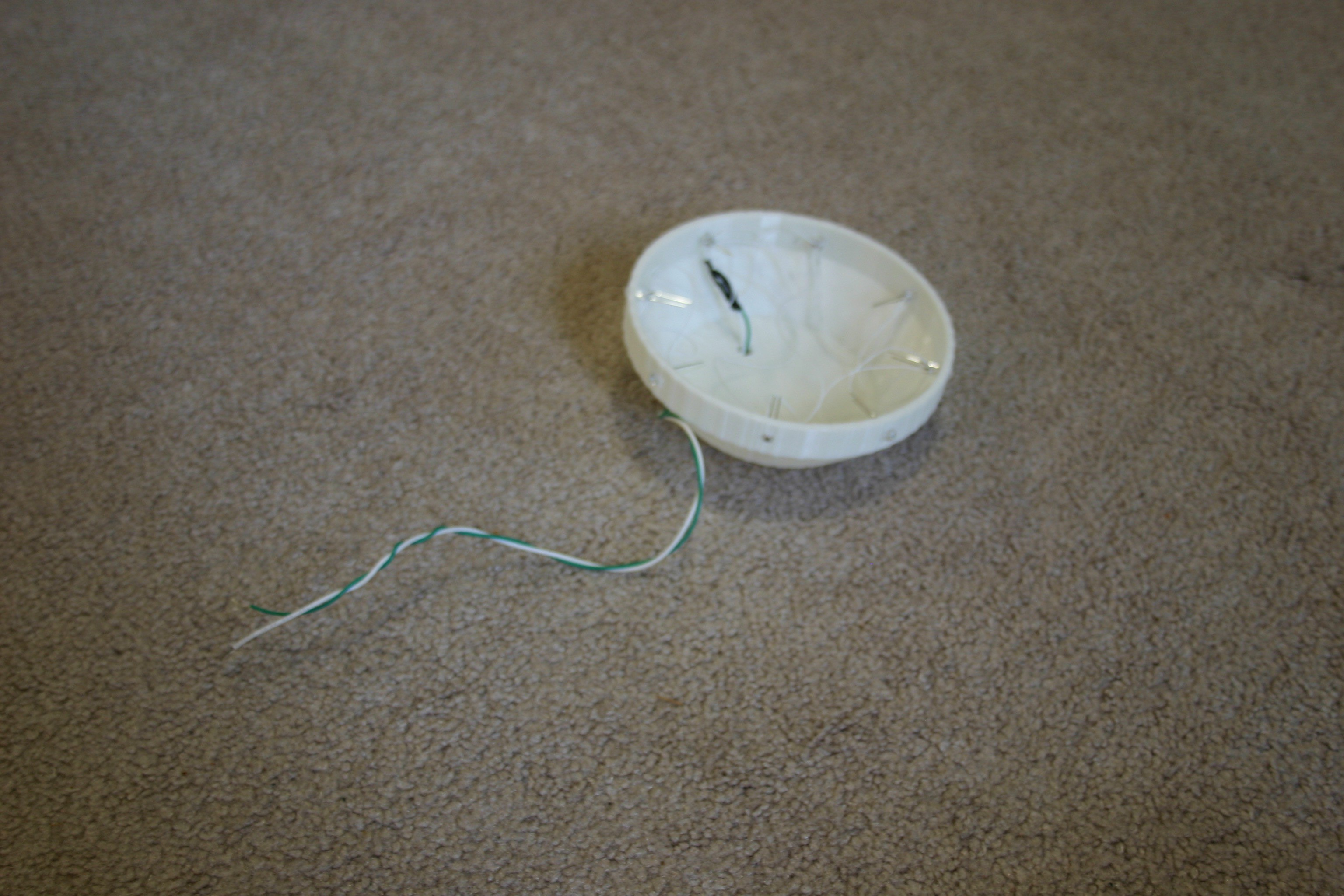
Below is the overview schematic of the charging (home) station. When Blinky arrives for refueling, the "arrived sensor" (probably a micro switch) will cause the servo controlled "claws" to grip the "charge rods" on Blinky. The "claws" will be lined with a conductor. The R2 contact will close and the current limited power supply will build the voltage up to 5.4 volts, at which point the claws will open and the "depart sensor" (probably a light) will let Blinky know that it is time to back out and roam again.

hand_right.STL

This is from the "Poppy" open source biped robot project https://www.poppy-project.org/en/technologies/

Standard Tesselated Geometry - 8.08 MB - 04/19/2017 at 23:15

Download

forearm_right.STL

This is from the "Poppy" open source biped robot project https://www.poppy-project.org/en/technologies/

Standard Tesselated Geometry - 5.66 MB - 04/19/2017 at 23:14

Download

ino - 5.96 kB - 04/19/2017 at 17:51

Download

- 35.24 kB - 04/11/2017 at 23:07

Download

- 125.16 kB - 04/11/2017 at 23:07

Download

View all 16 files

  • 2 × 1/4 inch by 2 1/2 inch bolts Used as charging rods
  • 2 × Nextrox Mini 12V DC 60 RPM High Torque Gear Box Electric Motor Found on Amazon.com
  • 2 × Eureka Vacuum Belts Found on Amazon.com
  • 1 × Pixy camera available on amazon.com
  • 8 × fast blink led's --microtivity il602 found at amazon.com

View all 14 components

  • Waving Arm for Blinky

    Mike Rigsby04/20/2017 at 00:21 0 comments

    I ran across a cool project, "Poppy", an open source bi-ped robot complete with all manner of 3d print files and instructions. I printed one hand and arm--then knew that Blinky needed this to provide a friendly "wave."

    I slid the hand into the arm and fastened them together using 2-56 machine screws.

    I attached the arm to a servo horn using 2-56 machine screws and nuts.

    I printed a bracket to hold the servo motor and attach to the ultracapacitor frame.

    I placed the servo motor in the frame and secured it with 2-56 machine screws and nuts.

    I attached the arm to the servo motor using the servo horn screw.

    I press fit the bracket onto the back of the ultracapacitor frame. I'll secure it and work out the control electronics and software in a later phase.

  • Line Detect Sensor

    Mike Rigsby04/19/2017 at 17:56 0 comments

    In this step I am adding two infrared line detectors--part of the homing system to reach the charging station.

    First, the sensors are mounted to the line detect holder.

    Next, the holder is melted to the front bumper of Blinky.

  • Moving Toward Home

    Mike Rigsby04/05/2017 at 17:22 0 comments

    Blinky now has vision and is able to move toward a "home" target.

    The camera is connected to the motor controller according to the schematic below.

    Here's what the top of Blinky looks like with his two Arduino controllers.

    We're not approaching the target color in a controlled manner that would allow for docking--but stay tuned. The vision and motor sketches for the Arduinos are posted on this site.

  • Power

    Mike Rigsby04/02/2017 at 18:51 0 comments

    Today I work at providing onboard power for Blinky. Print two "ultracap ends" and two "ultracap screw bases."

    Melt the screw bases to the ultracap ends.

    Insert the capacitors and place the assembly onto the chassis of Blinky. Mark the holes for drilling in Blinky's chassis.

    Drill the holes in the chassis.

    Print the switch holder.

    Drill holes and mount the switch holder to the left rear portion of the capacitor holder.

    Solder a diode (blocking diode from capacitor to charging post) in the center of a connector wire.

    Fasten the anode end of the wire to the right front charging post.

    Secure the capacitor assembly to the chassis with nuts and bolts.

    Print the top bracket and fasten the dc to dc converter to the bracket.

    Place the bracket on top of the capacitors. Install the on/off switch in the switch holder.

    Connect the capacitors, diode and dc converter as shown in the schematic (see overview schematic in details section), then charge the capacitor.

  • Blinky Head

    Mike Rigsby03/31/2017 at 20:05 0 comments

    Blinky's head started as a "flying saucer toy" design for Santa's Shop (Santa's Shop will be upgraded and placed on public display in the Brightway Insurance window in Gainesville, Fl during December of 2017). I tried to make the flying saucer "float invisibly" using magician's thread (which is pretty darn hard to see), but the thread will only support about 1.5 grams of weight. Instead of floating, the flying saucer will "rise and land" by means of a linear actuator (under construction right now).

    I have digressed. Blinky's head is composed of a lower piece as shown below:

    The holes for the leds are a little small and need to be drilled or reamed out. Using wire wrap wire, I connected eight multicolor fast blinking leds in parallel, then pushed them through the holes in the base piece.

    I soldered the wire wrap wires to about 10 inches of connector wire and drilled a hole in the bottom of the base through which the connector wires are routed.

    Print the top of the saucer head:

    Print the camera base:

    Melt (use soldering iron) the camera base to the top of the saucer (head).

    Melt the top of head assembly to the bottom of the head.

    Fasten the camera to the camera base using M3 x 12 machine screws and nuts.

    Fasten the head assembly to Blinky's chassis by melting the pieces together.

  • Wheels

    Mike Rigsby03/30/2017 at 23:24 0 comments

    In my previous projects, I purchased metal brackets to mount the motors. I considered designing my own bracket for 3d printing, but I usually search thingiverse.com first and I found a great bracket here:

    Print two of these brackets.

    Mount the motors to the brackets using M3 x 6 machine screws.

    Solder a .1 microfarad capacitor across the motor leads.

    Mount the motors to the body using machine screws and nuts.

    Route the wires through the hole to the back of the assembly.

    Print two wheels (at least 50% infill) and push the Eureka vacuum belts (tires) onto the wheels.

    Push the wheels (friction fit) onto the axles.

  • Add Bumper/Charge Pickup to Base

    Mike Rigsby03/28/2017 at 18:56 0 comments

    Print the bumper/charge rod piece.

    Drill a hole in the base to match the hole in the bumper piece (for future wire routing).

    Fasten the bumper and the base together with machine screws.

    Obtain (2) 1/4 inch by 2 1/2 inch bolts.

    These thread into the bumper piece (they will be the charging rods for Blinky).

  • The Base

    Mike Rigsby03/28/2017 at 14:08 0 comments

    Print the base at 30% infill.

    Drill two holes (yes, I should have designed them into the base--but I'm not perfect), then secure the caster base using m3 machine screws.

    Push the caster ball into the caster base.

View all 8 project logs

Enjoy this project?

Share

Discussions

Morning.Star wrote 03/31/2017 at 08:44 point

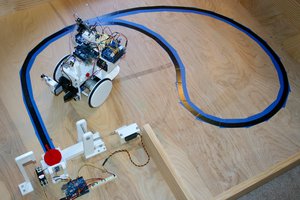
Great robot, really inspiring power system treating energy as food.

I'd suggest a small pair of EPM tractors in the charging station to make the power contacts with. You could fine-tune the position to hook up using a Hall sensor, and you only need to get close. Magnets make great electrical connections because of their nature, I use them as battery terminals regularly.

Using controllable magnets though, means once charged, the station can then release Blinky's charge port so it can disengage. Its just a pulse from a capacitor to switch the magnet on and off inductively and isnt part of the charge circuit.

https://en.wikipedia.org/wiki/Electropermanent_magnet

  Are you sure? yes | no

Mike Rigsby wrote 03/31/2017 at 16:11 point

That's an interesting concept which I will explore.

  Are you sure? yes | no

Josh Valdes wrote 03/30/2017 at 23:52 point

I have long fantasised about making a robot that could find its charging station, feel free to bounce ideas off me :D

  Are you sure? yes | no

Mike Rigsby wrote 03/31/2017 at 00:19 point

I'm optimistic about making this work. My "Pretty Useless Machine" can zero in very accurately on a small target, so I've succeeded in enough pieces of the recharging puzzle to believe that I can put it all together. On the commercially available side, "Chip" and "Cozmo" sort of recognize chargers, but aren't autonomous. Roomba works, but I want to understand a system and be able to adapt it to my robots (maybe a biped in the future). I appreciate your offer and I'll be throwing out some "any suggestions?" questions to you as I attempt to overcome the weak points (and possibly simplify or cost reduce the system).

  Are you sure? yes | no

deʃhipu wrote 03/31/2017 at 07:30 point

I guess in the worst case you can just have a charging rail along one wall -- that should be an easy target ;-)

  Are you sure? yes | no

RoGeorge wrote 03/25/2017 at 15:16 point

+1 for the look. Don't know why, but that shape seems familiar.
:o)

  Are you sure? yes | no

Similar Projects

Does this project spark your interest?

Become a member to follow this project and never miss any updates