 Mike Rigsby
Today I work at providing onboard power for Blinky. Print two "ultracap ends" and two "ultracap screw bases."
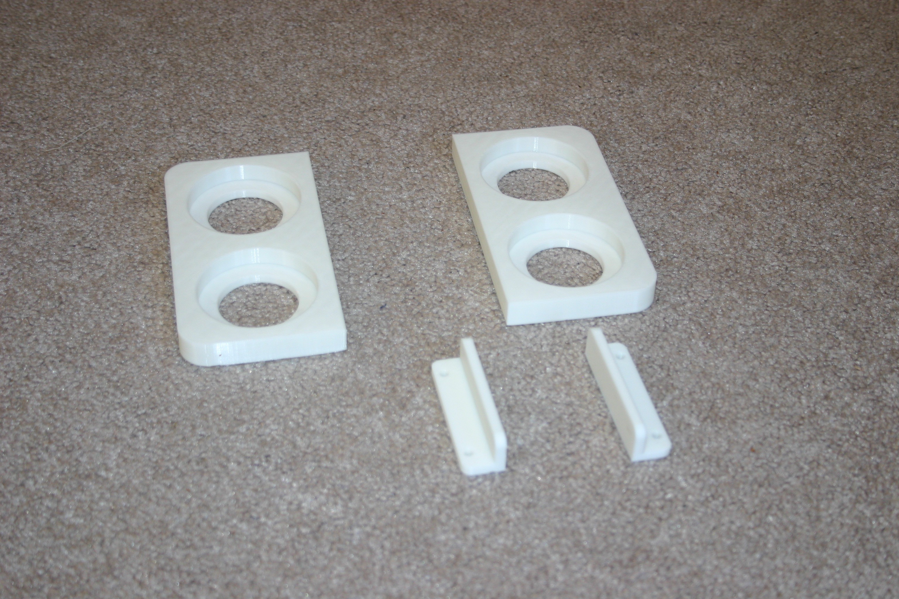
Melt the screw bases to the ultracap ends.
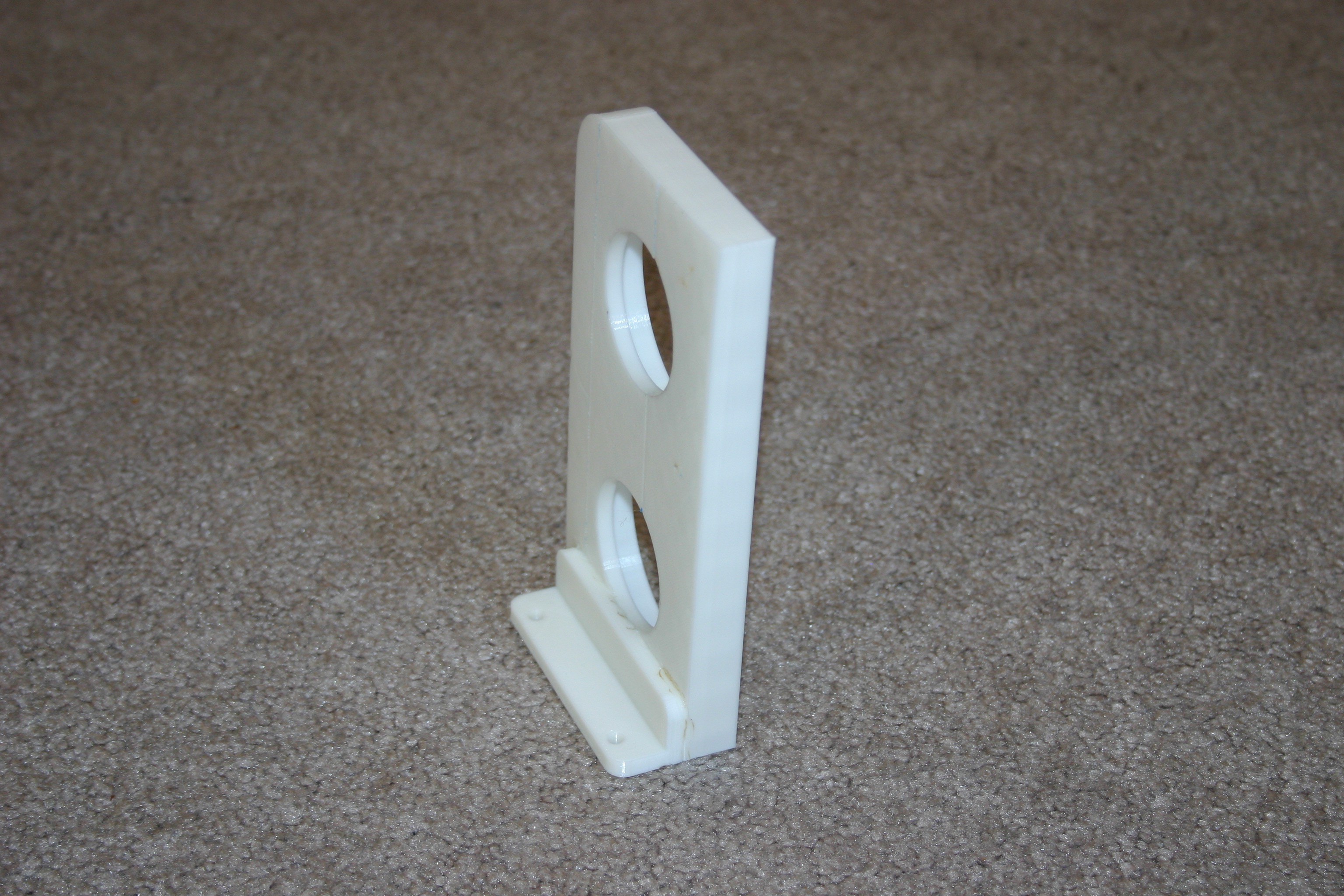
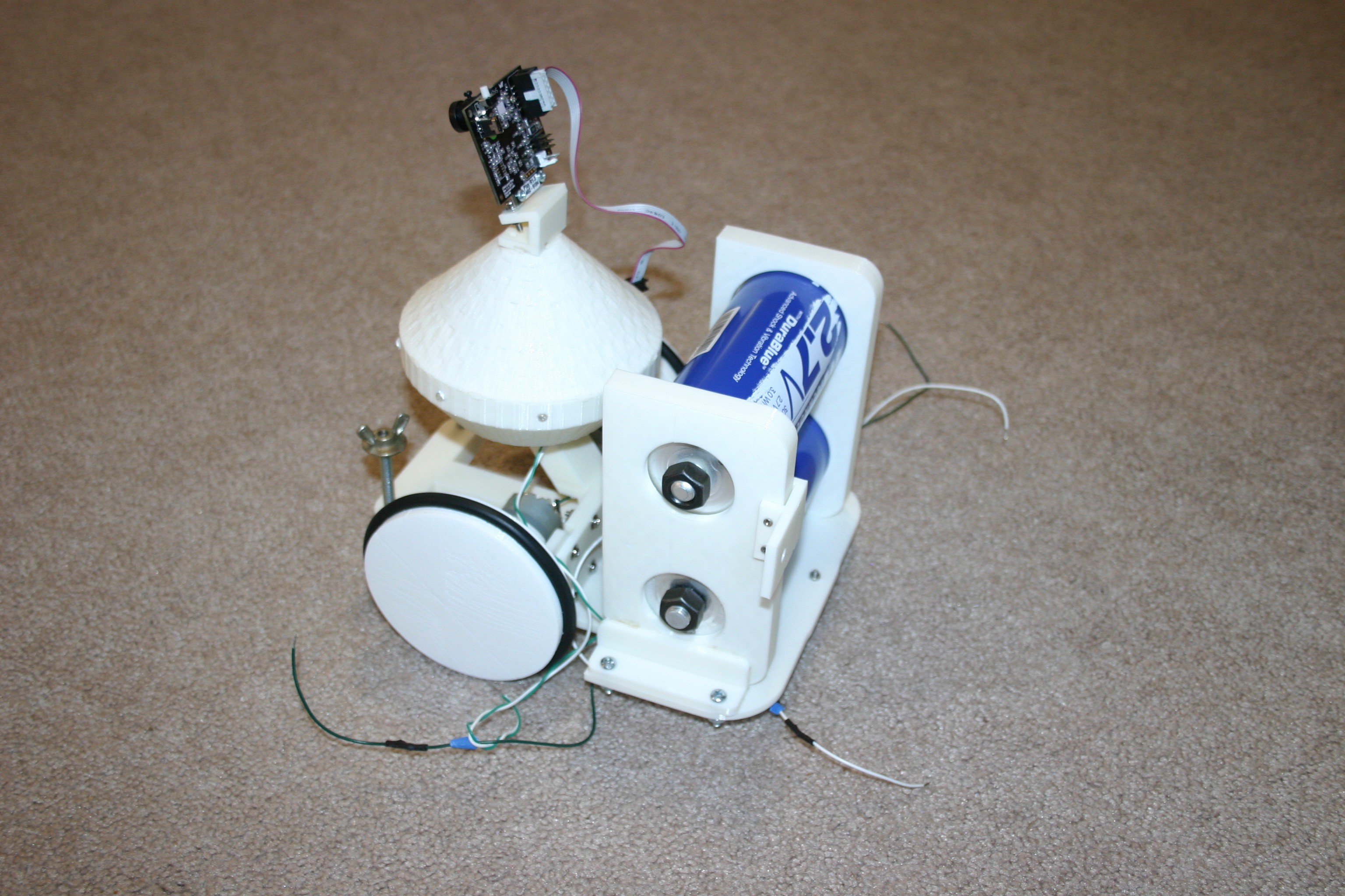
Insert the capacitors and place the assembly onto the chassis of Blinky. Mark the holes for drilling in Blinky's chassis.
Drill the holes in the chassis.
Print the switch holder.
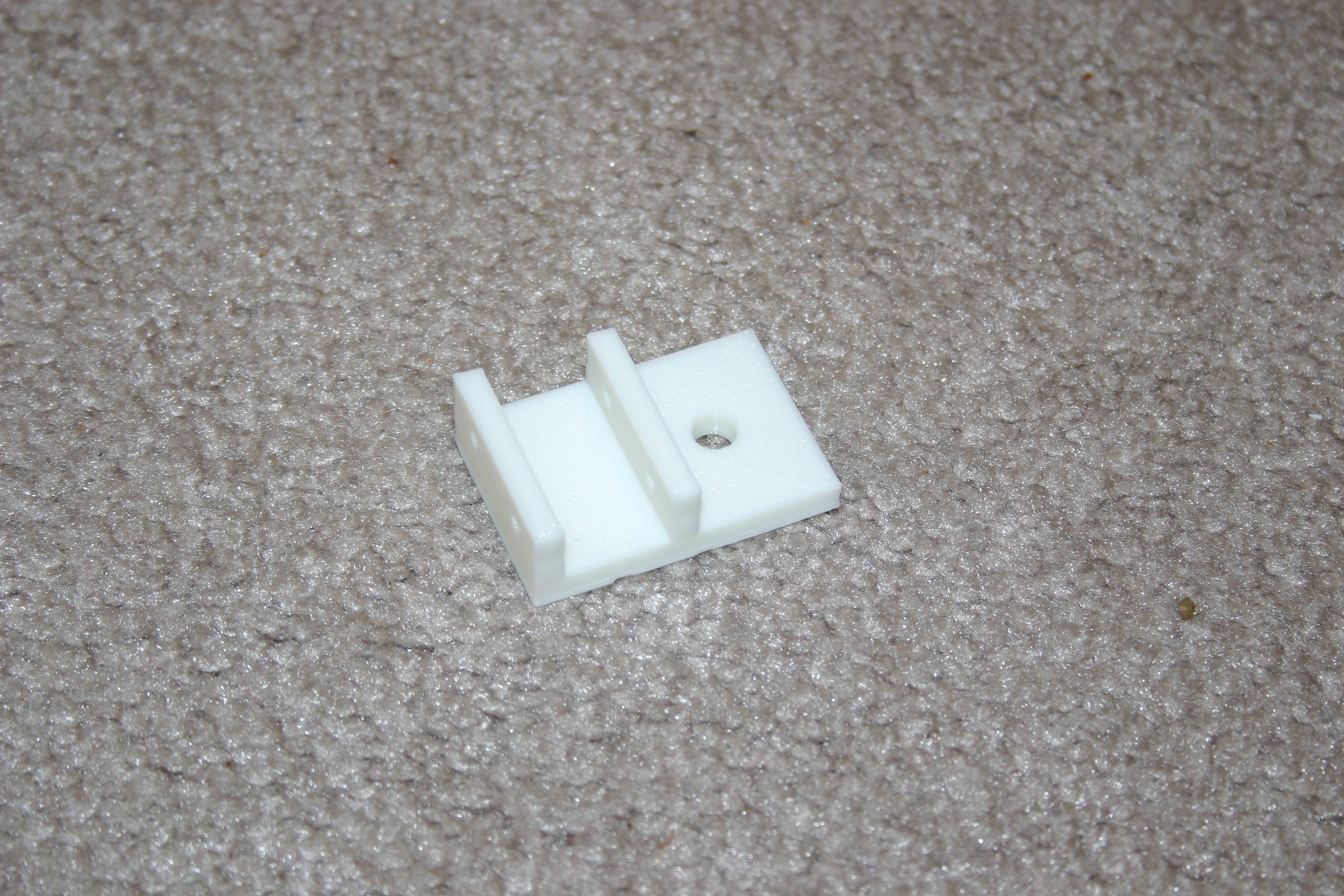
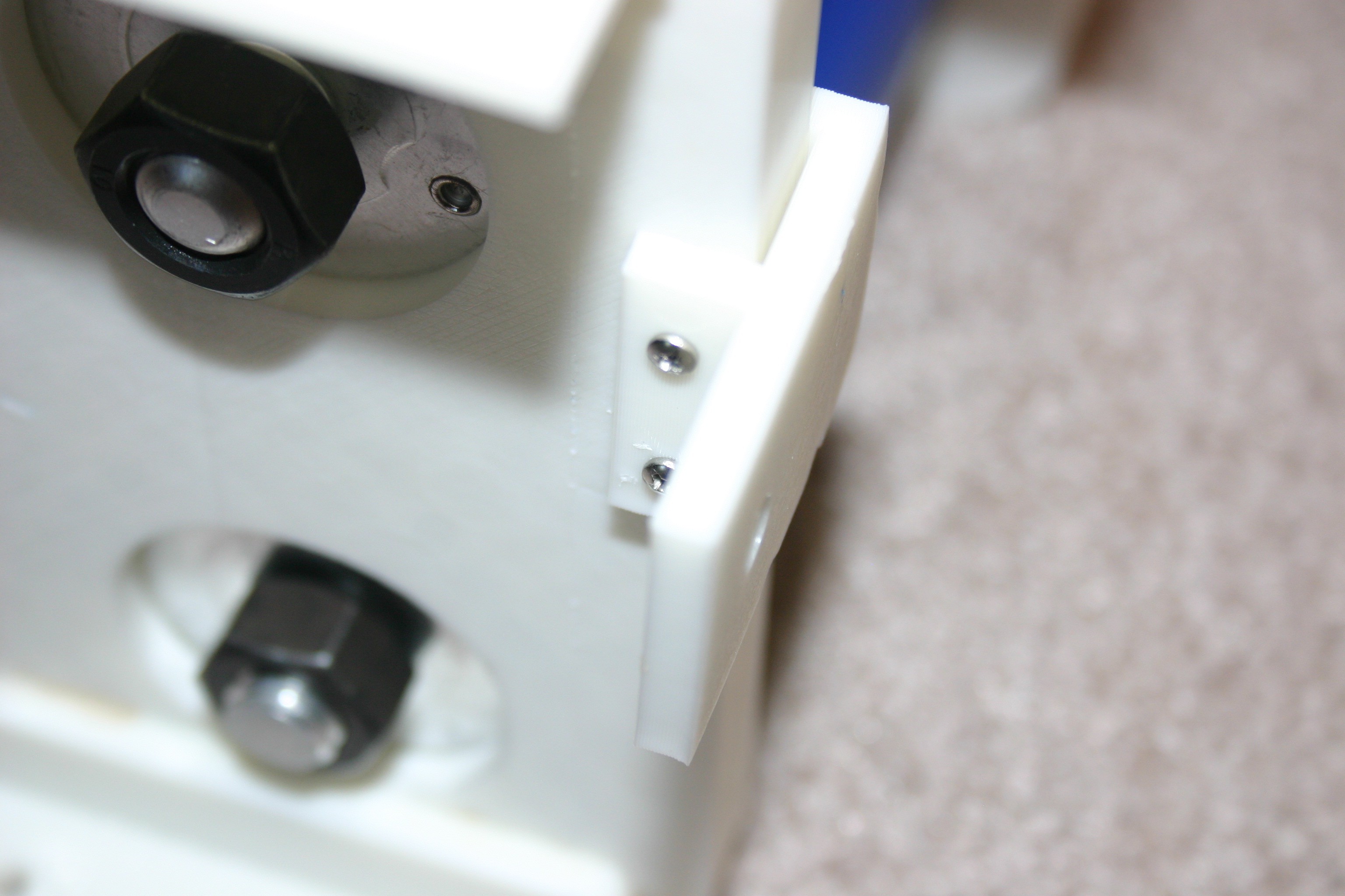
Drill holes and mount the switch holder to the left rear portion of the capacitor holder.
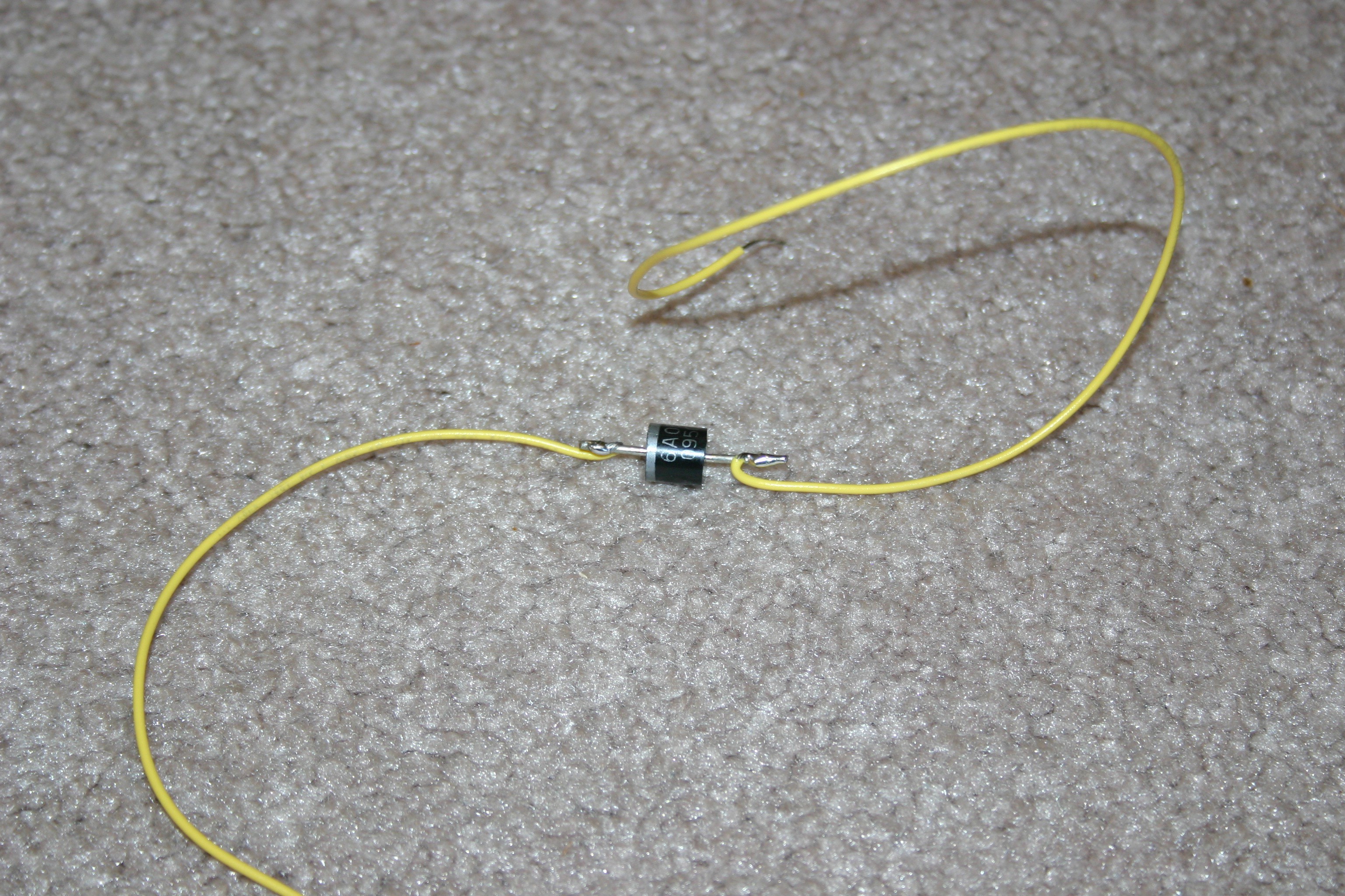
Solder a diode (blocking diode from capacitor to charging post) in the center of a connector wire.
Fasten the anode end of the wire to the right front charging post.
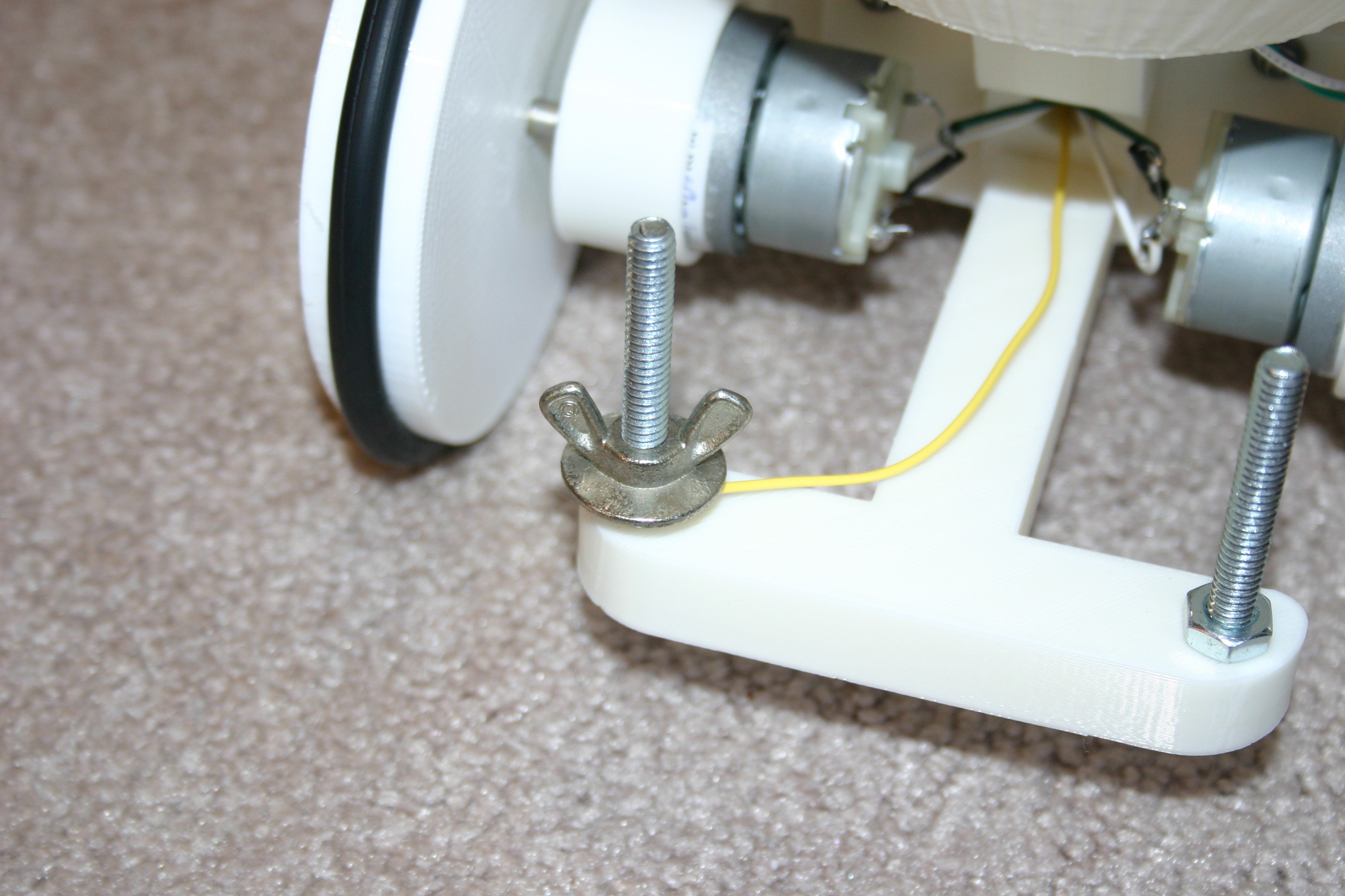
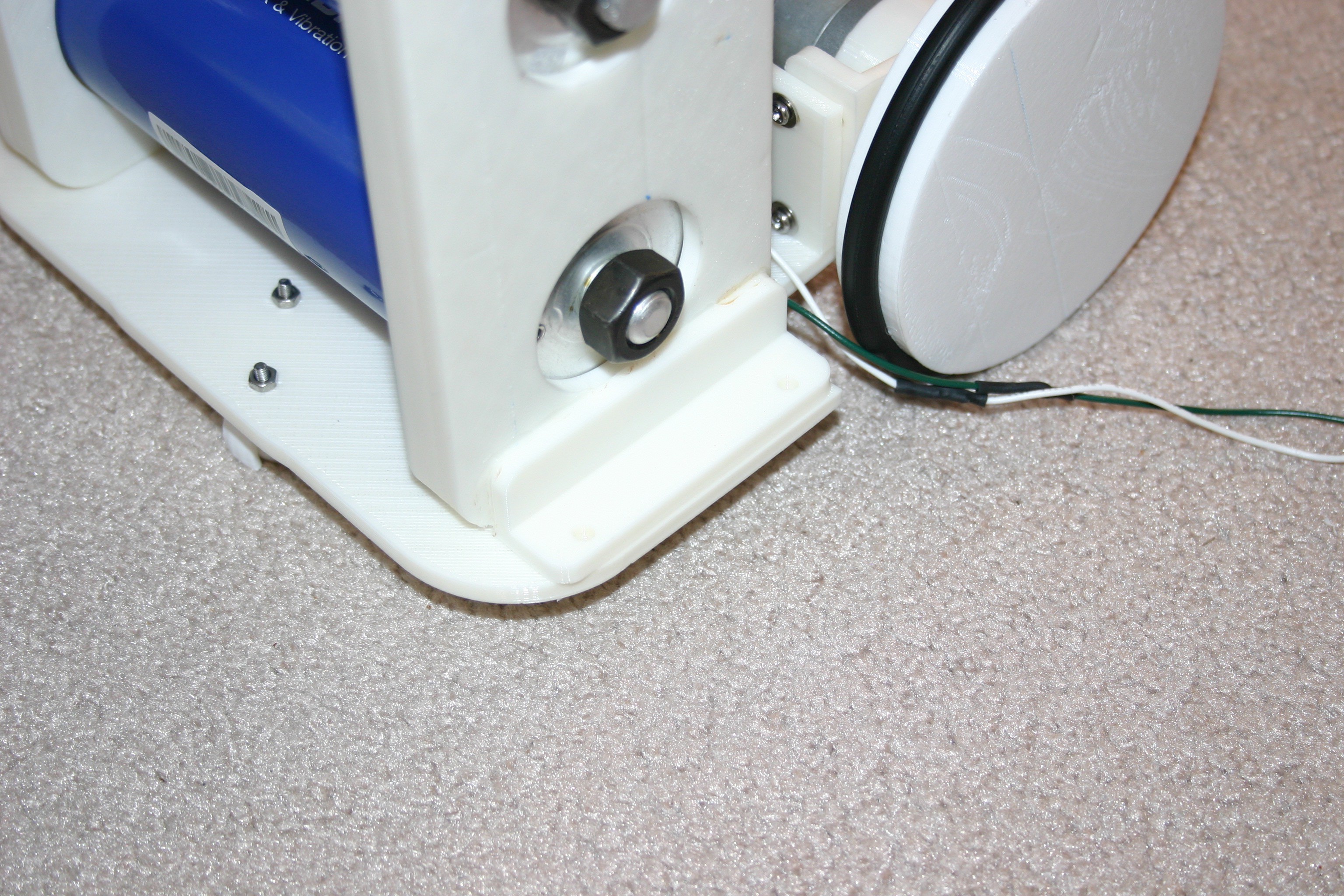
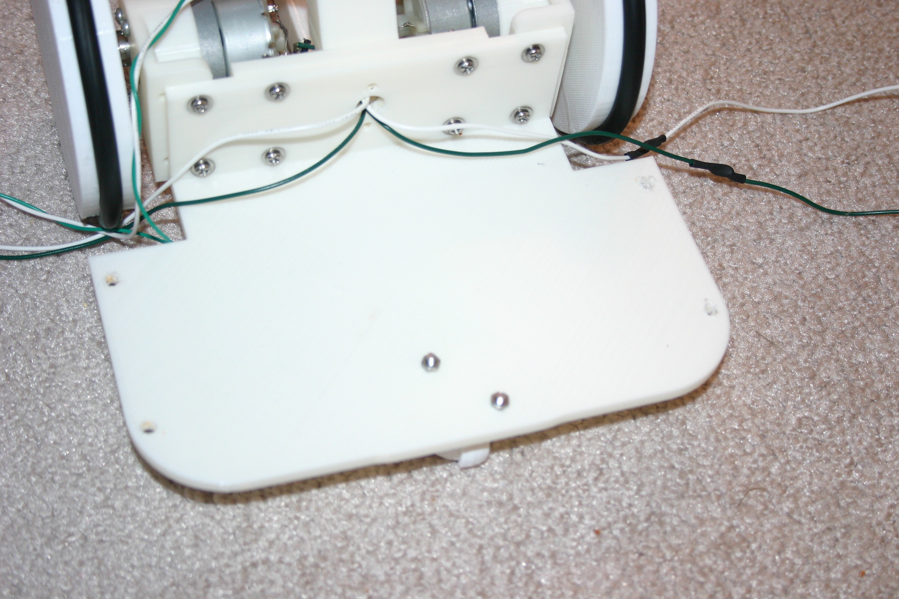
Secure the capacitor assembly to the chassis with nuts and bolts.
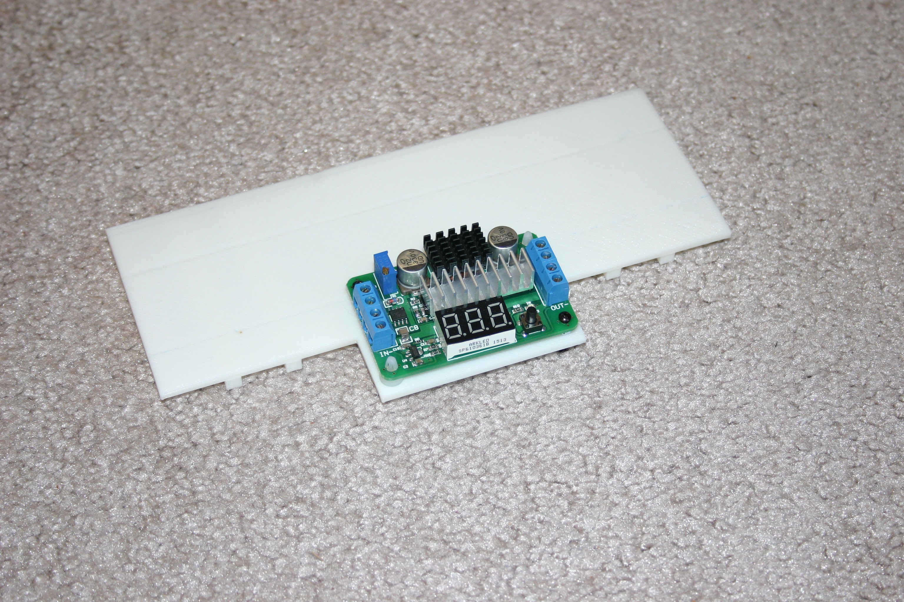
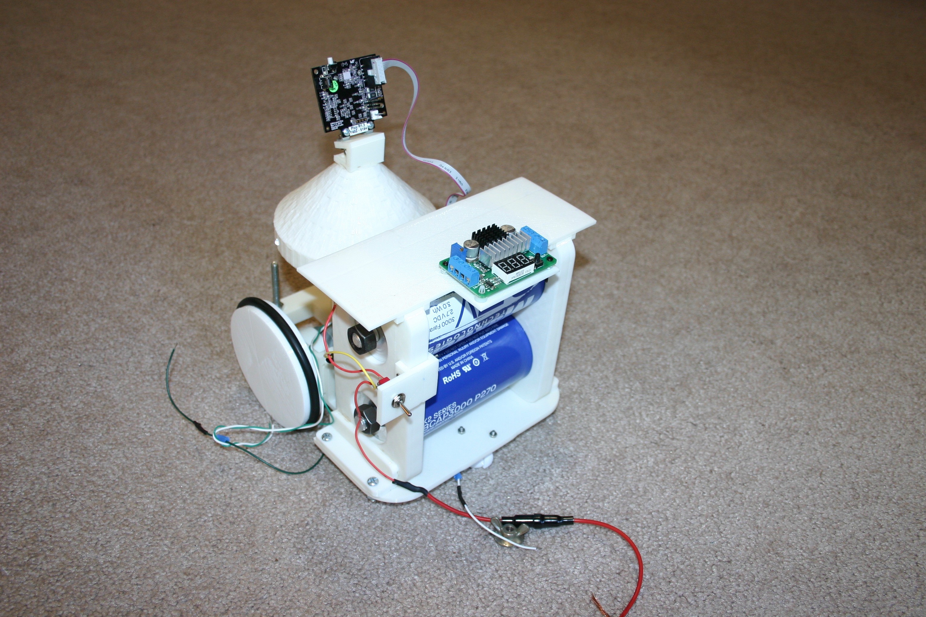
Print the top bracket and fasten the dc to dc converter to the bracket.
Place the bracket on top of the capacitors. Install the on/off switch in the switch holder.
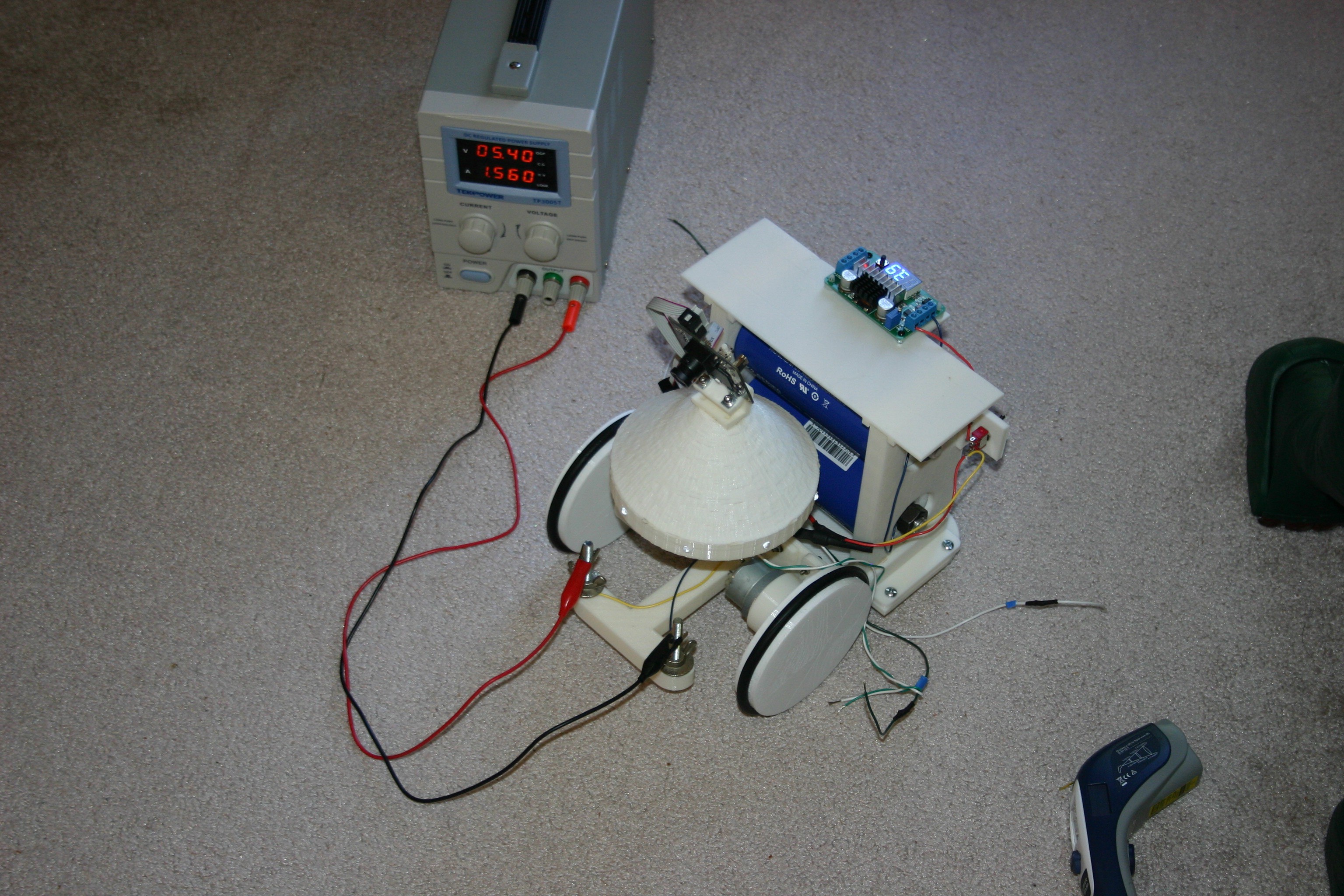
Connect the capacitors, diode and dc converter as shown in the schematic (see overview schematic in details section), then charge the capacitor.
Discussions
Become a Hackaday.io Member
Create an account to leave a comment. Already have an account? Log In.