Sorry for the late post, I've been a bit busy. I did manage to finish designing the board by the end of the week of the last log. Incoming photos:
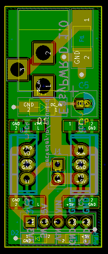
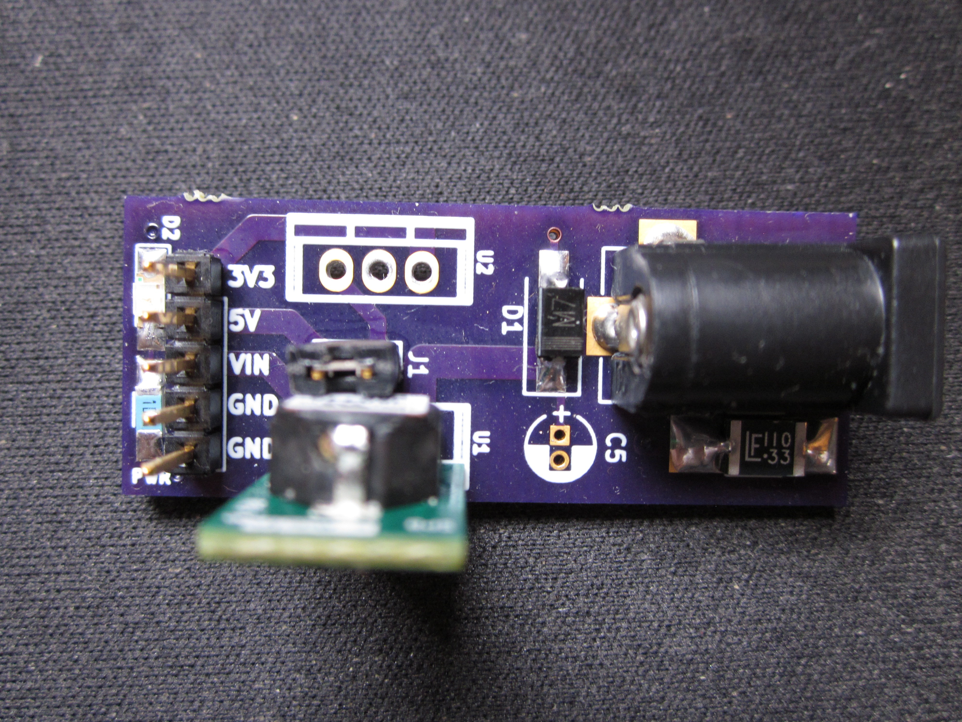
I still haven't come up with the exact model linear regulator to use for the 3.3V rail just yet. Overall I'm happy with the design so far. I did add a footprint for an optional electrolytic cap on the input, just in case and I had the board space to spare. I wanted t to add in a few more things such as some reverse-biased diodes across the outputs of both regulators to provide protection against inductive loads, but I wanted to keep the board size (cost) down.
If I were to make any changes, I would likely move the "PWR" label close to the actual LED(or just swap around the resistor and LED footprints), possibly move the polyfuse to the input positive terminal vs connecting it to the ground terminal, and increase the resistor value that I used for the LED even more as my LED was still on the bright side when I used a 1K resistor.
Parts list for the deluxe version:
1206 sized resistor (recommend a 1K+ value)
1206 sized LED
2.1 mm Barrel Jack
5x1 2.54 mm pin header
2x1 2.54 mm pin header
1 pin jumper
oki-78sr-5/1.5-w36-c 5v regulator (most expensive item other than the PCB itself)
1812L110/33MR 1812 size polyfuse
3.3V reg model tba
caps for the said 3.3V reg tba
Discussions
Become a Hackaday.io Member
Create an account to leave a comment. Already have an account? Log In.