 iliasam
At this step I have printed at 3D printer laser holder. This small part is used to hold the laser at certain position.
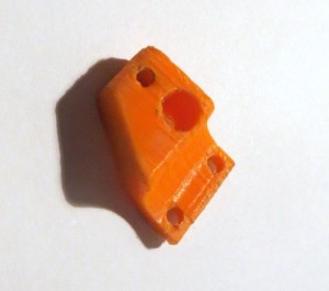
Photo of the laser holder:
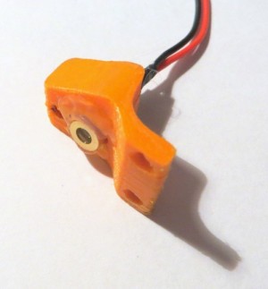
I glued laser to the holder with hotmelt.
Photo of the holder with the laser installed:
Last step is to fasten the laser holder at PCB. It's done with two M3 screws.
Photos of assembled PCB:
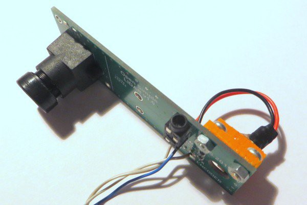
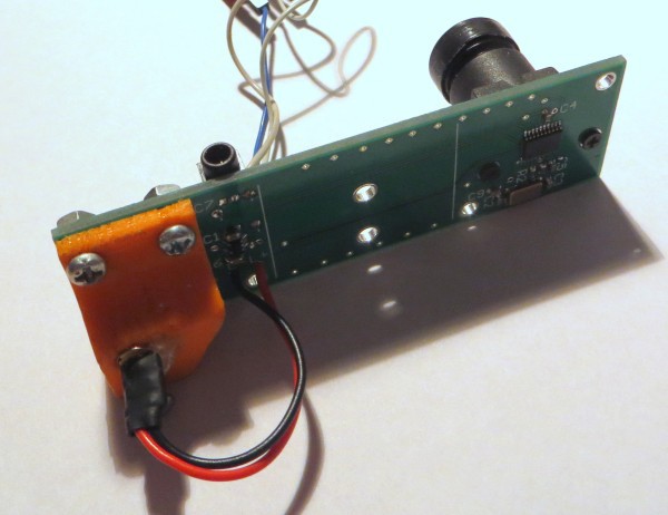
Angle between the laser and the lens axis is specially calculated. It must be near 11-12 degrees.
Optical alignment.
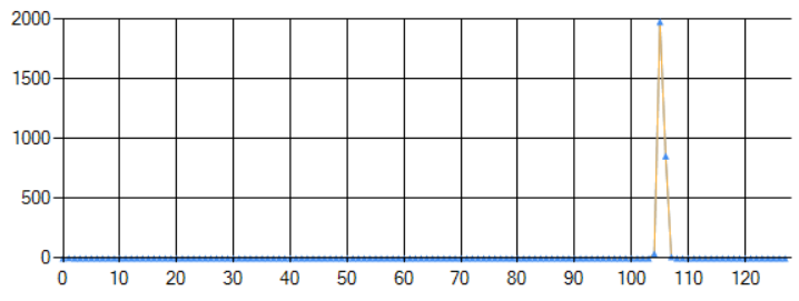
To get the LIDAR properly working I need to align it's optical elements. First step is focusing lens. Focusing is done by rotating the lens till the image in PC utility don't became fine.
Photo of not focused image:
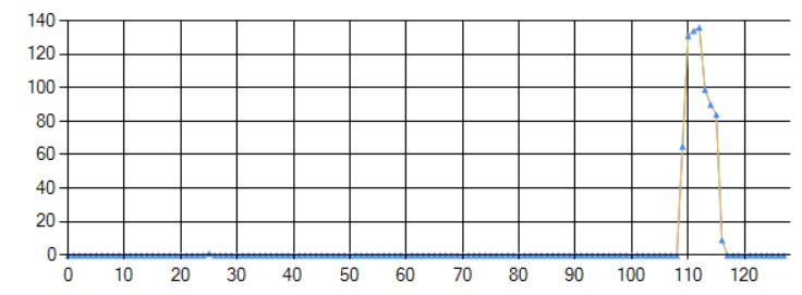
Photo of focused image:
When the lens is set to best position it must be fixed by special screw which is twisted to the lens holder (it must be special hole in it).
Next step is laser alignment. It is done by special screw than must be placed at lower hole of laser holder. The purpose of laser alignment is to get best amplitude of received signal. This alignment must be done at maximum LIDAR's distance (3-4m).
Discussions
Become a Hackaday.io Member
Create an account to leave a comment. Already have an account? Log In.