Close
0%
0%

Siemens SIKIT-DK 8080

This mid-70s version of the Arduino needs to be put together and then put to work!

Similar projects worth following
124 views
0 followers
A few years ago I was given this NOS boxed Siemens System SAB 8080 SIKIT-DK. So now for the 50th anniversary of the newest IC that was in there, it's about time to put it together and make it do stuff. It's basically the mid-70s version of the Arduino. 8080 CPU, 256 Bytes of RAM, 24 I/O lines. I also don't know what to do with it yet. An idea would be an EPROM editor for 2708 tri-voltage EPROMs as I have tons of EPROM burners, some 80s vintage, none can burn 2708 - and I have some 2708s to burn eventually. I might do some experiments like adding video capabilities. Or just serial. Definitely parallel as I will probably want to burn entire 2708s, not just dump them to RAM, edit them, erase them and write them back. (yes I know I need more than 1k of RAM to edit 1k of ROM)

Current status: I haven't even started yet. Don't worry, that's about to change.

So what's to do?
- Find out if the ICs are any good (Spoilers: I've tested most of these when I got the kit and all but one RAM chip were fine. Didn't test the monitor ROM, couldn't test the clock generator, couldn't test that weird interface chip under the CPU, and the 8255 behaved a little weird in certain positions, but worked fine in others. The CPU ran Space Invaders for a little while. The 8255 was reading joystick inputs fine in a Scramble arcade machine, but in the position where it interfaces the sound chips, the sound was a bit odd at times. I put that to the combination of gold legs and the cheapest sockets 1982 could buy)

- Build the board according to the instructions - except for RAM. As I mentioned, one of the supplied RAMs was dead, and 256 Bytes is not enough for much of what I want to do with it, also it has sockets to install up to 1k of RAM, I would like to use 2114s or go even higher.
- Get the system to work by typing in the examples (minimal viable system)

- Make it do useful work (do you have ideas what to do with this thing?)

My ideas for what to do with this thing so far:

I'm a major repair technician at a local arcade and pinball machine museum. I currently have 5 devices capable of burning EPROMs, some of which are from the 80s. None of them can program tri-voltage chips like the 2708 (or TI's infamous TMS2716 of which I have 5 blank ones). We also have tons of circuit boards, long story short we have two Space Invaders bootlegs that won't run and one that does. The one that does has code on ROM0 NOPed out and if I put that chip in any of the others, they also work. I guess that's some copy protection (for a bootleg...). So I want those to work without whatever weird contraption it must have been connected to which was lost to time in order to boot.

Since eventually I might have to burn entire 2708 ROMs, would be cool if I could hook it to a slightly more modern computer and copy files over parallel or serial. Don't need to go the other way since I made an adapter that allows reading two 2708 as a 2716 (of course you need an external PSU supplying the extra rails).

What else? I don't know. Maybe interfacing it with a 6845 CRTC and display video. Maybe give it 8k of RAM and map it so that it can run the original Space Invaders code. (the CPU already played Space Invaders, that's what I tested it in). Maybe run BASIC. If you have some ideas, please comment.
  • The kit is complete and working

    senily64dx • 09/22/2026 at 21:44 • 0 comments

    That took a little longer than it should, and it's all due to my stupidity. I managed to forget to hook up the Output Enable from the 2111 to the 6116 RAM chip and in the meantime, tried different addressing schemata which didn't work and I ended up ANDing the outputs from the RAM mux and since that's working and I'm also using all the chips from the box (except for the blank 2708) which will probably end up going in an arcade machine where a single 2708 completely died, rendering the screen black&white except for the sprites. Another part sacrificed to fix an arcade machine.

    So it now has 2k of RAM. Due to my addressing issues, it's in two disjoint areas, one at 1000-13FF and the other at 3000-33FF.

    The Siemens made components are all a bit slow. The UART is only stable to 4800 baud and can transmit but not receive at 9600. At 19200 it's completely dead.
    There's also three 74161 - the first one in the timing chain is made by AMD because the Siemens parts are just too slow. At least they run lukewarm - the AMD one gets almost too hot to touch.

    By the way, this kit is actually a licensed version (I hope) of the Intel MCS-80 aka SDK-80 dev kit. The Intel one was colored in Intel's corporate light blue. As you can tell, the Siemens one is orange-red. Siemens' capacitors from that era are also orange-red.

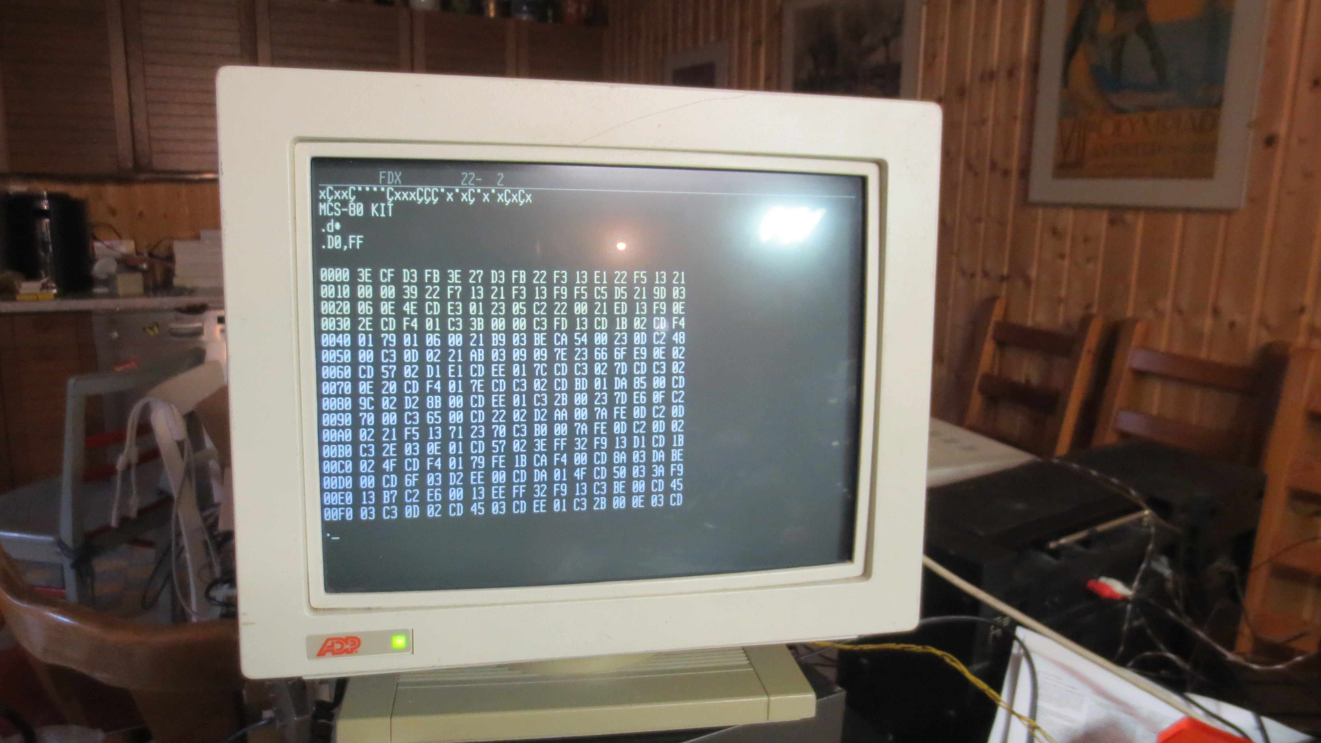
    The dumb terminal's screen shot shows the dump of the monitor ROM. I did dump it using a small contraption I made for reading two 2708 as one 2716. They won't program of course and if you tried, you'll probably fry the programmer. Also sorry about the dumb terminal. As the owner of a small computer museum, it's embarrassing that my only terminal is this modern (very early 90s vintage).

    So next I'll edit part 1 of the video (from the pre-build phase to the working machine) and publish it on Youtube.
    Part 2 will be about building and programming the EPROM programmer. It'll probably begin with some type-in example programs and testing of the 8255, which I still don't know if it's working (remember it's not dead but it may be borked)

  • Assembly complete

    senily64dx • 09/08/2026 at 21:23 • 0 comments

    I've finished assembling the machine according to the build manual which I'll probably have to scan in so anyone can build a copy.

    So far I've tested the power rails. While the 7905 was a bit hot at -5,8V during out-of-circuit testing, it did regulate well enough that I didn't think it would pose any problems. Now in the circuit I get -4,97V which is bang on no worries.

    I also tested the clock generator chip (bottom left corner) and it works. Haven't checked the exact frequencies but the oscillograph shows they're in the right ballpark. The two clock outputs to the CPU have odd duty cycles and 12V levels which I bet is what the 8080 needs (I know the 8080 needs a 12V clock).

    According to the manual, the 8251 UART can only go up to 4800 baud which is kinda lame, but the internet says it's fine up to 19,2kbaud which is what I have my dumb terminal set to anyway. Also the baud rate selector has two unpopulated spots which I bet were intended for 9600 and 19200. Of course I will run it at 4800 to see if it works and then go to 9600 and if that works, try 19200.

    You might have spotted I don't have the RAM or its MUX populated. I will start with known good 2114 which require putting in some jumpers and rewiring the RAM sockets. I might later populate the machine with known bad 2111 to test them - at least one of these passed in the tester but completely wrecked the machine it was in which took me like 6 hours to find.

    You might also have spotted I populated the two optional i8212 buffers/BUS transceivers. I have a bag full of those on hand and they need to be either jumped (for a minimal functionality) or populated (for full functionality). Since I intend to use this system for future stuff requiring more memory, I'll better put them in.

    Now I have another party this weekend so there's not much time for more work... I also have to clean the basement just enough so it's usable for party mode. My parents aren't too happy I converted their party basement into an electronics repair workshop...

    Full test next week.

    I've recorded 3 hours (in SD) of build footage (which I'll fast forward) and a few dozen minutes of other stuff (in HD). There will be (at least) two videos - one with the build process which will be released when the system has achieved the status of booting to the Machine Language Monitor and has at least proven that the basic functionality works (manually blink an LED on the 8255, testing RAM access), and another video when I have at least the EPROM programming functionality working.

  • Whoopsie - forgot to scan the PCB

    senily64dx • 09/02/2026 at 21:48 • 0 comments

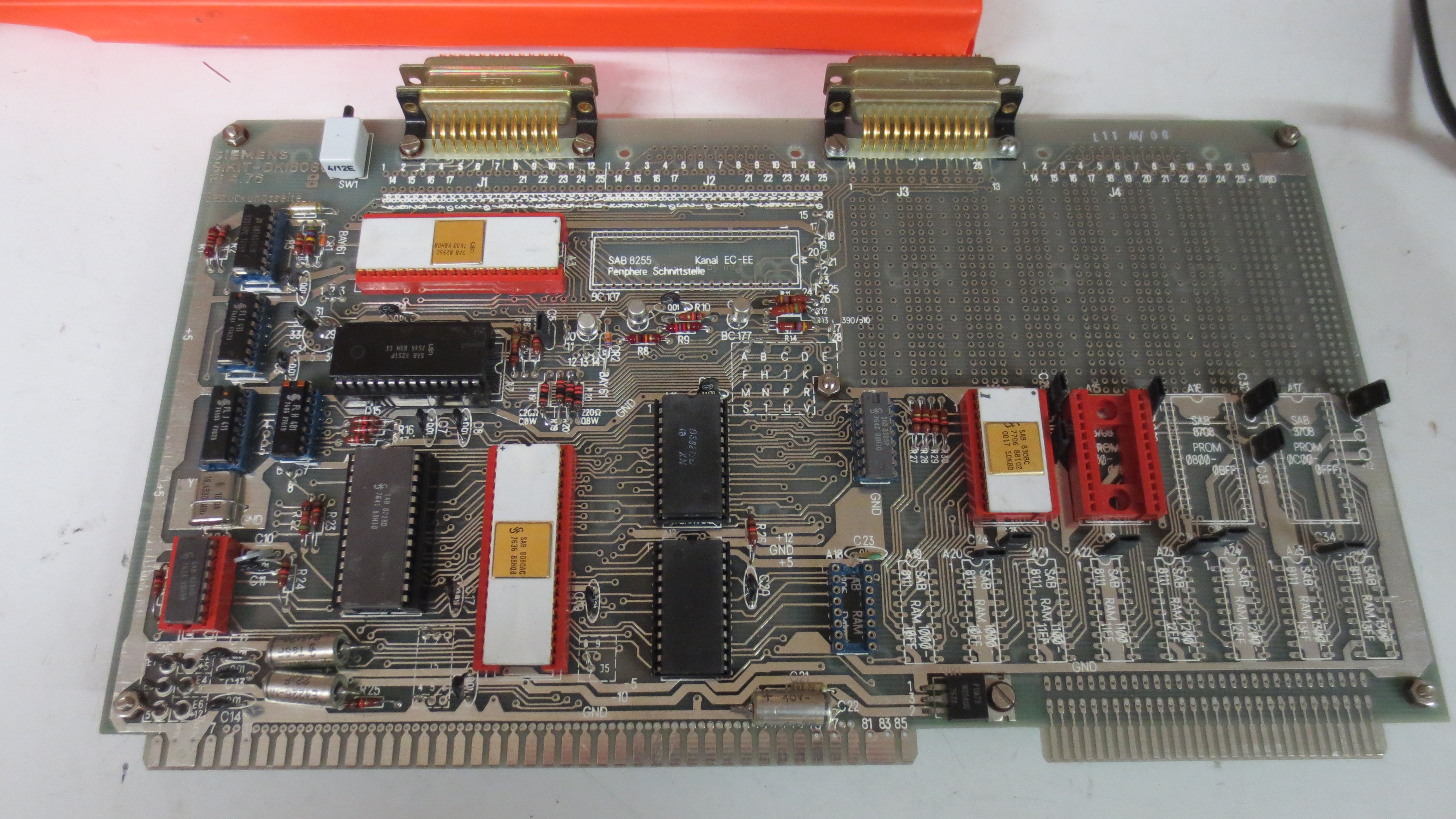
    Oops - after around 1 hour of populating components (video upcoming, probably next week or so), my brain told me it would have been a good idea to scan the bare PCB... well OK so I added scans of both sides of the PCB with partially populated components, better than nothing.

    The footage I shot so far does have a good look under the red IC socket that's populated in the scan, definitely good enough to see where the traces are going and what the silkscreen says.

View all 3 project logs

Enjoy this project?

Share

Discussions

Ken Yap wrote 09/09/2026 at 01:31 • point

Or you could modify your board for 2716 or 2732 and forget about the tri-voltage malarkey of the 2708. 

  Are you sure? yes | no

senily64dx wrote 09/09/2026 at 20:58 • point

I'm doing that all the time... modifying arcade games to run one big easy to obtain ROM instead of lots of super obsolete small ROMs, especially when said arcade boards came without ROMs. But here I have to make a small modification to one out of the six ROMs the boards come with and in that case I want to keep it original.

And sometimes, Retrocomputing is about keeping stuff as original as possible. So I want to be ready. Also I'm looking for a use case for this computer and this is the best I could come up with (besides maybe getting it to render a Mandelbrot on the dumb terminal). What if maybe one day I'm forced to keep it original? Or even better - program like it's 1976?

(also technically, I want to program the 2708, so I'm dealing with a QUAD-voltage malarkey. And I'm gonna enjoy it, believe me. Nerds have a weird definition of fun) I've once built a programmer for 7603 OTP 32 Byte PROMs (once programmed they're drop-in compatible to the 74xx188) out of a 555, two CD4017s and I forgot what the logic IC was, probably a 4070 or 4073 plus a transistor to switch the programming voltage. And two banks of DIP switches.

  Are you sure? yes | no

Ken Yap wrote 09/09/2026 at 21:25 • point

Hahaha, I know the nerdy feeling of doing this kind of stuff. All my projects are probably^wcertainly pointless but one has to occupy oneself with problem solving of one kind or another to ward off dementia.

  Are you sure? yes | no

Similar Projects

Does this project spark your interest?

Become a member to follow this project and never miss any updates