0%
0%
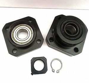
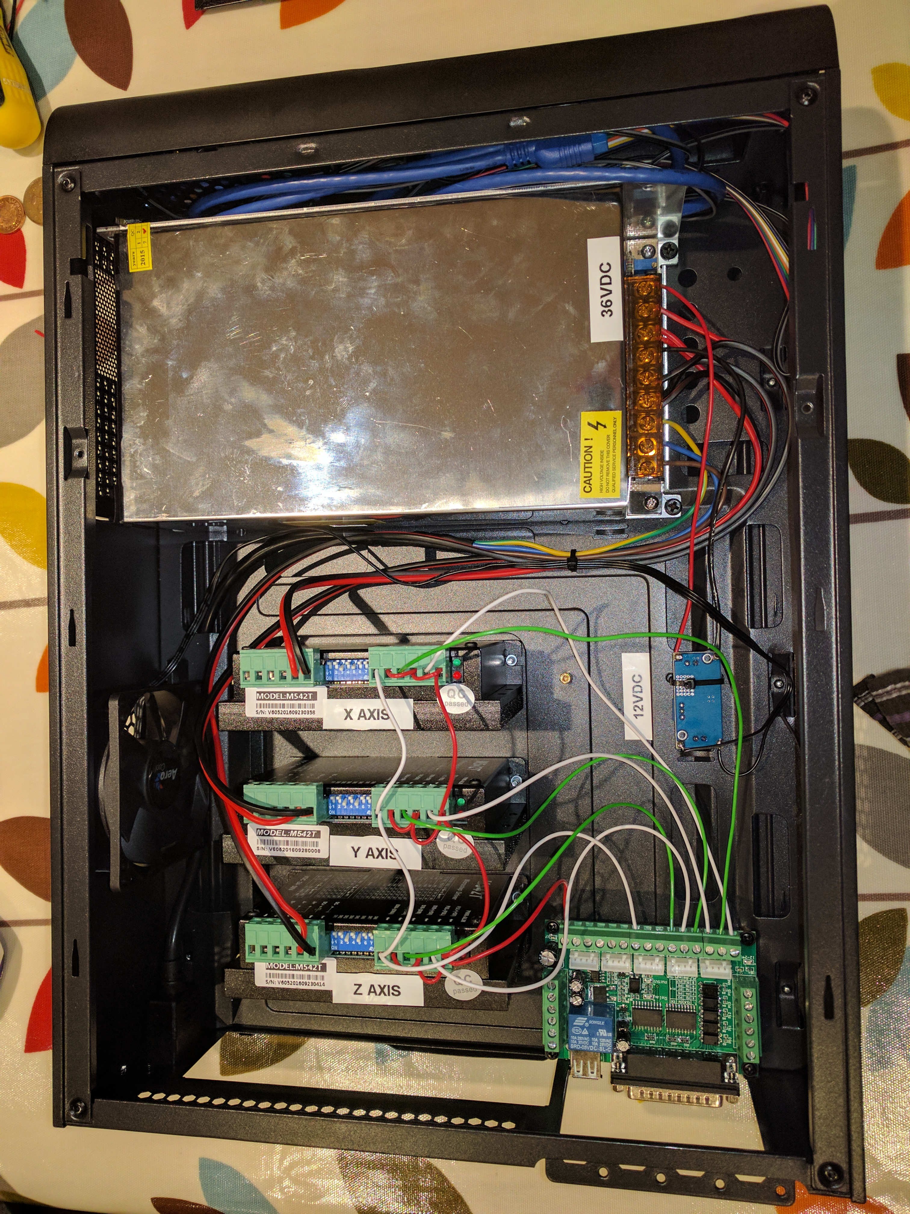
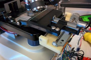
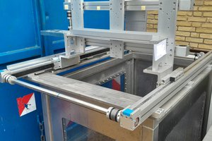
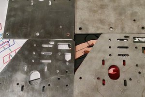
CNC Mill Conversion (RF30)
Makerspace Newcastle has an elderly, worn out RongFu RF30-clone mill. Let's freshen it up and CNC it :-)
 David Pye
Become a Hackaday.io member
Already have an account? Log in.
Just one more thing
To make the experience fit your profile, pick a username and tell us what interests you.
Pick an awesome username
hackaday.io/
Your profile's URL: hackaday.io/username. Max 25 alphanumeric characters.
Pick a few interests
Projects that share your interests
People that share your interests

 charliex
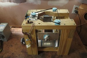
 dekutree64
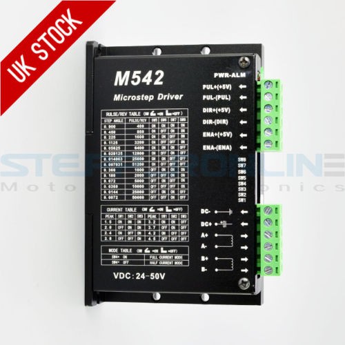
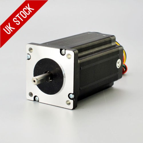
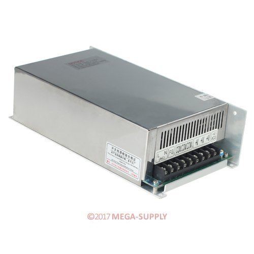
Nice write up. Did this project come to fruition? I want to convert mine to CNC and start buying the parts necessary. Ive seen a few directions people have gone with different stepper/servos and controllers from Mach to Fastcutcnc. Id like to see a youtube video running and over view of the completed project if you have a link. Thnks.