 David Pye
'm currently working on plans for CNC conversion of the X-Axis and installation of a ballscrew and ballnut.
Like the Y Axis, I plan to use a 20mm 5mm pitch ballscrew.
At the moment, I don't have the ability to machine things very accurately (existing X axis backlash is horrendous!), I am using flanged ballscrew supports (FK15 and FF15) and paying the supplier of the ballscrews to turn them down and thread them to fit the flanges.
The flanges for mounting the ballscrews look like this:
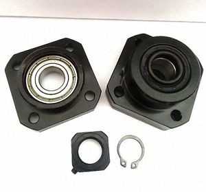
The FK flange has a securing nut to tightly grip the ballscrew so it can rotate, but not move backwards or forwards. The FF flange simply supports the ballscrew but doesn't stop it moving backwards or forwards. The reason it isn't tightly secured at both ends is to account for change in its' length due to thermal expansion.
For the X axis, as you look at the machine, I am going to fit the FF15 leadscrew support on the LEFT hand side of the X axis table, and the FK15 and stepper motor mounting onto the RIGHT side.
X axis ballscrew mount - left hand side
For the FF15 bearing mount, I have designed the following plate (which I am machining out of 3" x 1/2" thick Alu bar):
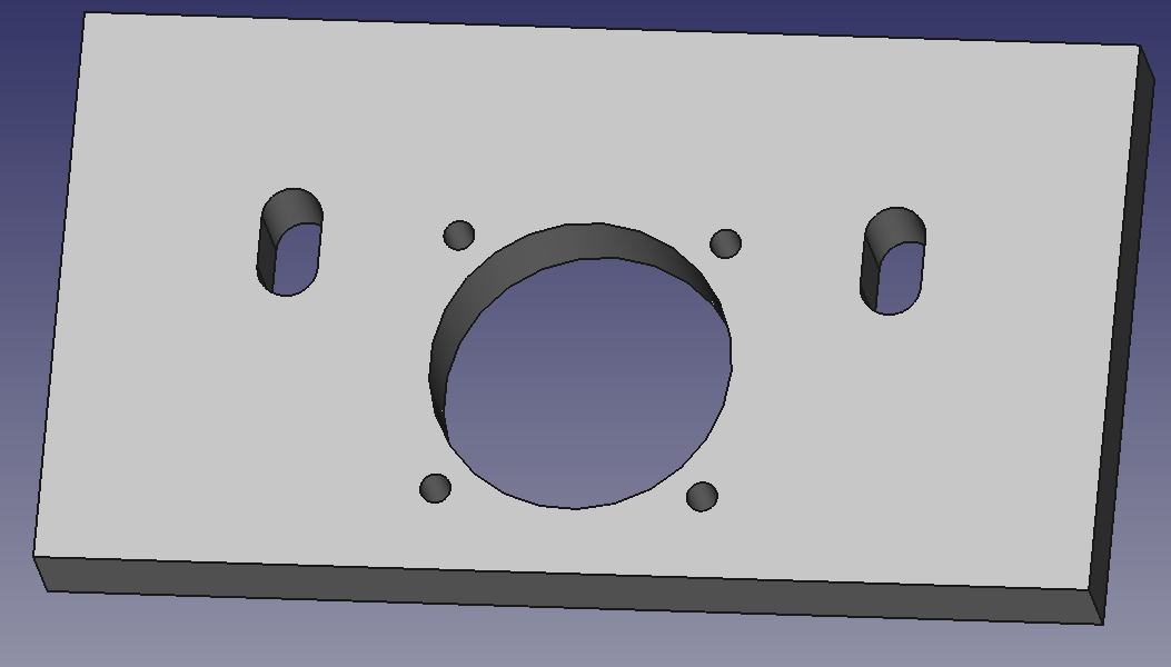
This has a centre hole and four M4 drill holes (which I will tap out to M5) to take the FF15 flange. The two slots are for mounting to the X axis table using the existing mounting bolts and will allow some adjustment in the vertical position of the plate.
X axis ballscrew mount - right hand side
This mounting is a bit more complicated, and consists of FOUR pieces of milled aluminium bolted together.
Plate 1:
Firstly, a plate similar to the FF one, which bolts to the mill table using the existing bolts: This one is slightly thicker, and is made of 3" x 3/4" thick bar.
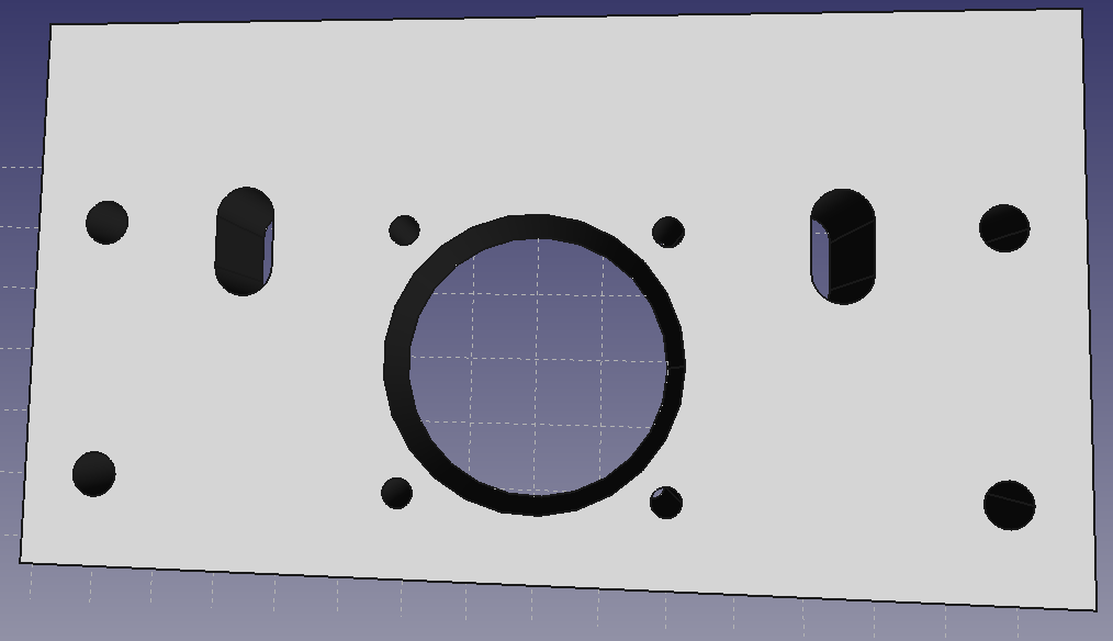
Main differences here are:
Thicker plate (15mm) as the FK15 bearing mount is thicker and it needs to be contained within the plate ideally.
Four additional holes (countersunk at the rear of the plate) to take M6 allen head bolts to bolt the spacer plates on, which will then themselves secure to the motor mount)
Plates 2 and 3 - spacer plates
The spacer plates are 60mm 'high', 10mm thick and the appropriate length to accommodate the shaft of the ballscrew, the flexible coupling, and the stepper shaft.
They are tapped to take M6 bolts to attach them to the FK15 mount plate shown above.
CAD files and exact length specifications pending!
Plate 4 - Stepper mounting plate
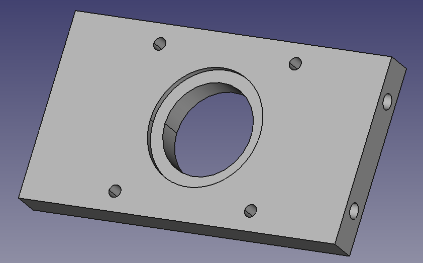
This plate bolts to the two spacer plates and completes the FK15 and stepper mount assembly. The stepper motors I am using are NEMA24, so the hole spacing etc is made to suit it.
This plate is also machined from 3" x 1/2"thick Alu barstock. It has a mounting hole for the stepper motor shaft to protrude through, a bored out 'lip' that the stepper motor centering 'lip' sits into, as well as four tapped holes for the M5 mounting bolts to hold the stepper in place:
Once I've machined and assembled these, I will post photos which will make things a bit clearer!
Discussions
Become a Hackaday.io Member
Create an account to leave a comment. Already have an account? Log In.