 Lauri Pirttiaho
Instead of the original self test board which, according to the description in the manual, is a board that is plugged into the external memory board edge socket and connected with the DIL40 connectors of the target cable to the target connector socket, this self test board will be a DIL40 hack plugged directly into the target socket and connected with a single cable to the memory socket for the 5V supply (pin B of the external memory connector P1).
The 100 kHz oscillator will be a 200 kHz RC oscillator made with dual unbuffered 7404 gates (NL27WZU04) and a divider made of single D-flop with inverted output (SN74AUP1G80). The concept is like shown in this simulation.
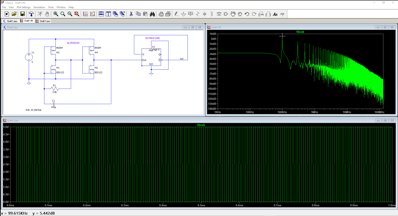
Lacking the models of actual components the actual frequency will be seen by measuring the live circuit.
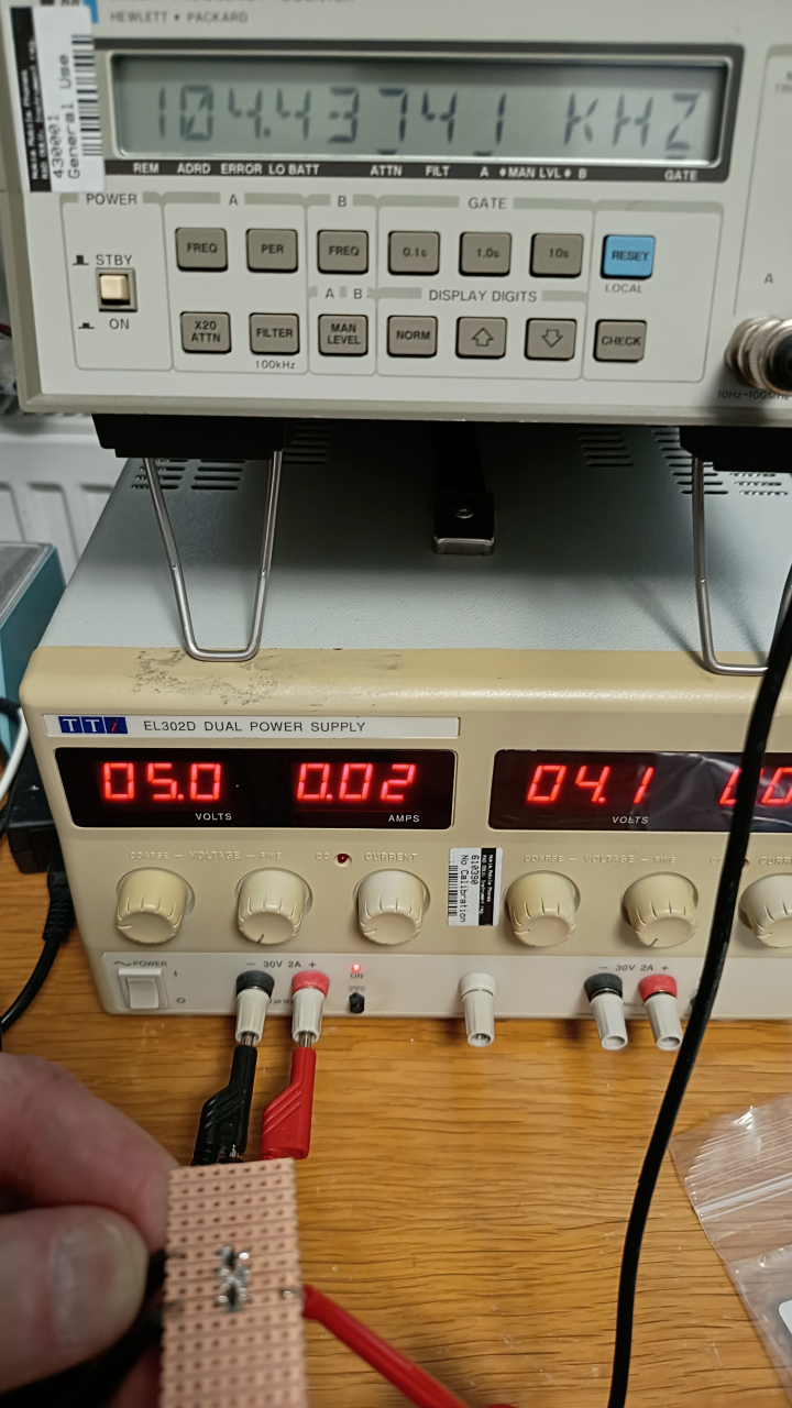
After building the circuit C=470pF and R=8.2 kΩ resulted in 104 kHz.
Discussions
Become a Hackaday.io Member
Create an account to leave a comment. Already have an account? Log In.