 Lauri Pirttiaho
The original plan for the minimal target board was just the CPU, oscillator, and TC5517A with address lines A8-10 grounded for 256 bytes of memory. It was a small change to add TPA clocked capture FFs for those address lines for full 2 kB.
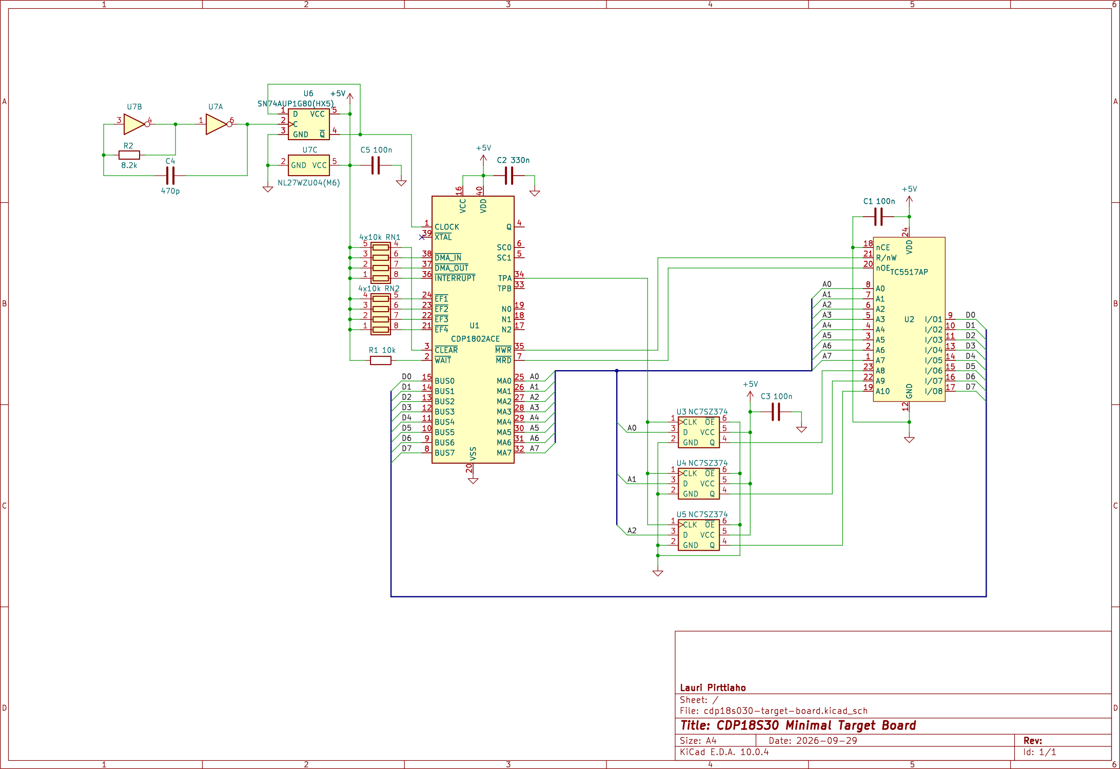
Initially the target board turned out to have a serious flaw, as it was not possible to handler the ZIF socket lever.
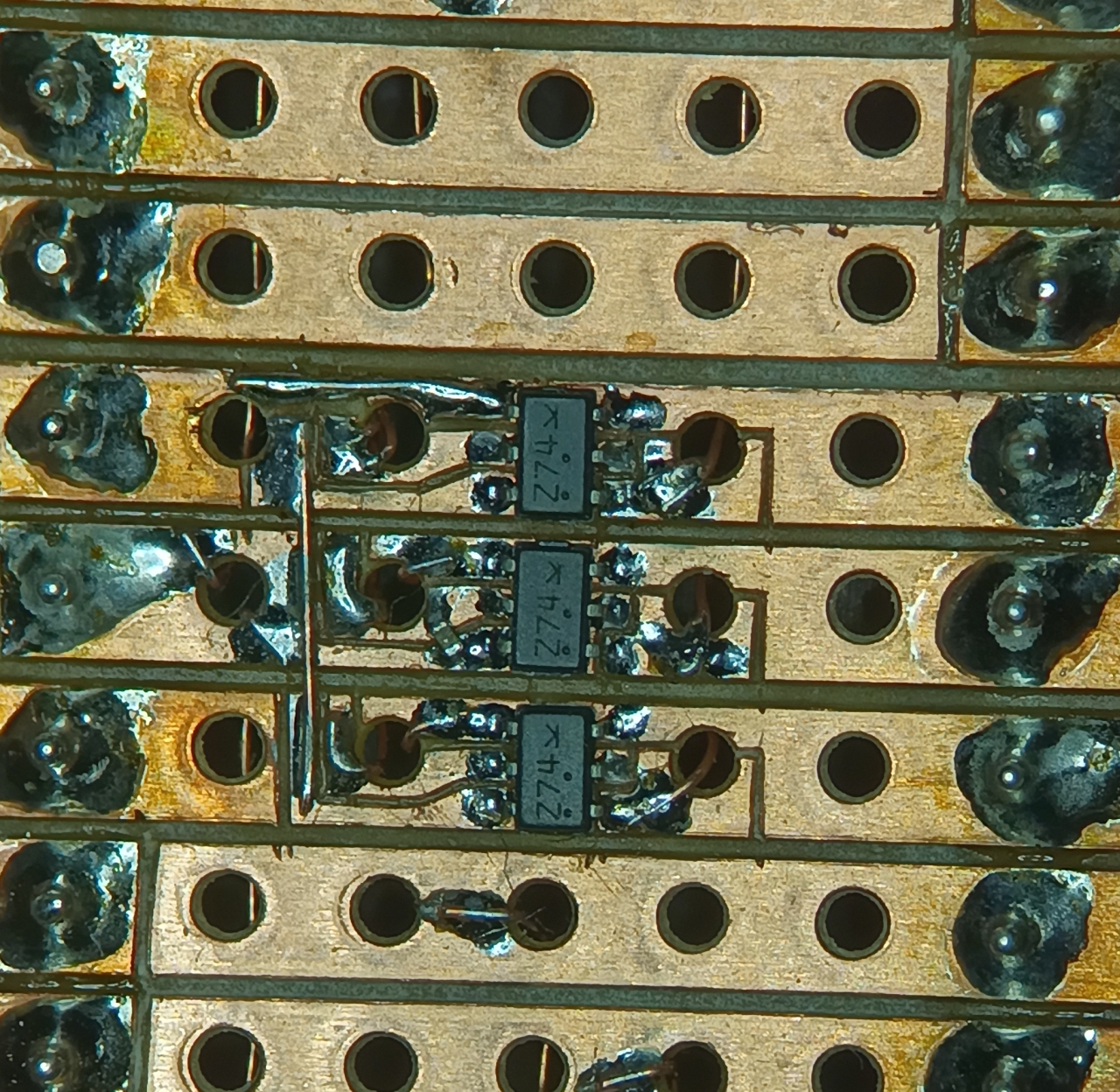
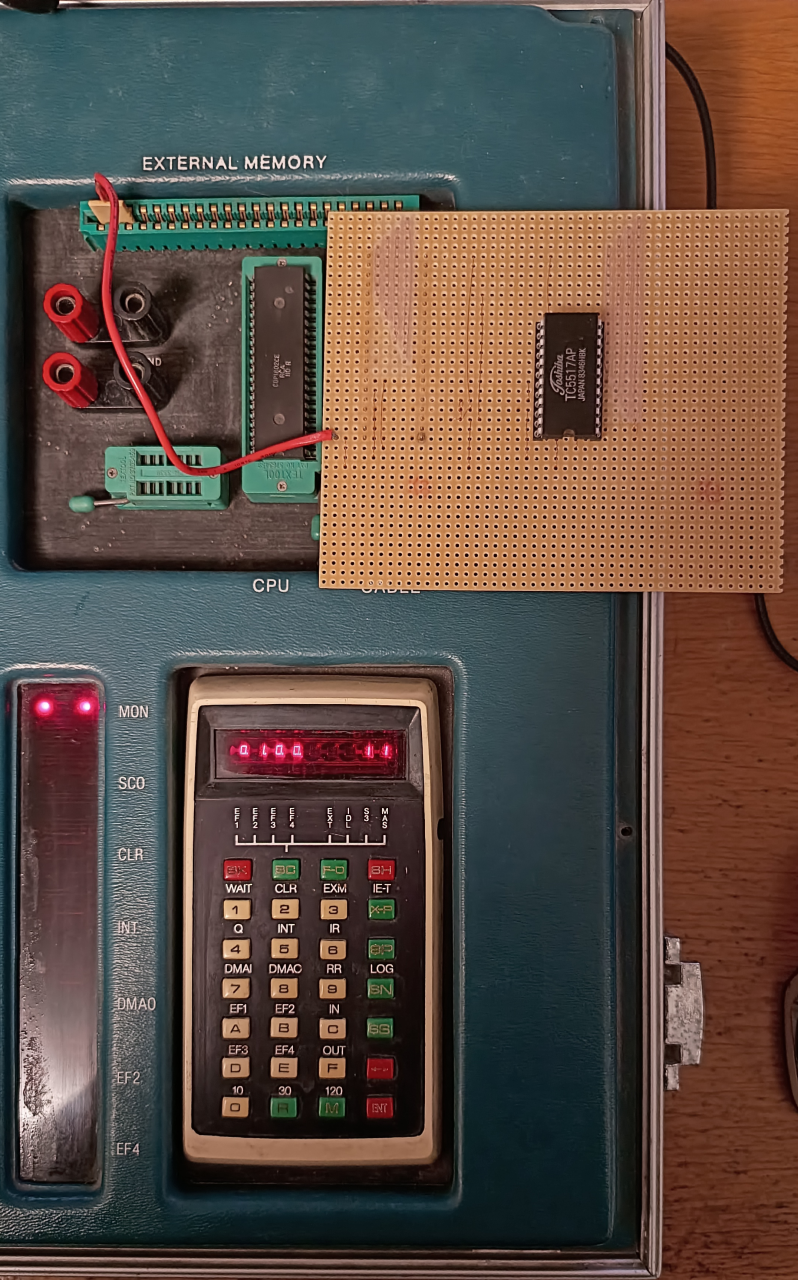 Other components than the memory are SMDs and thus on the copper side of the board.
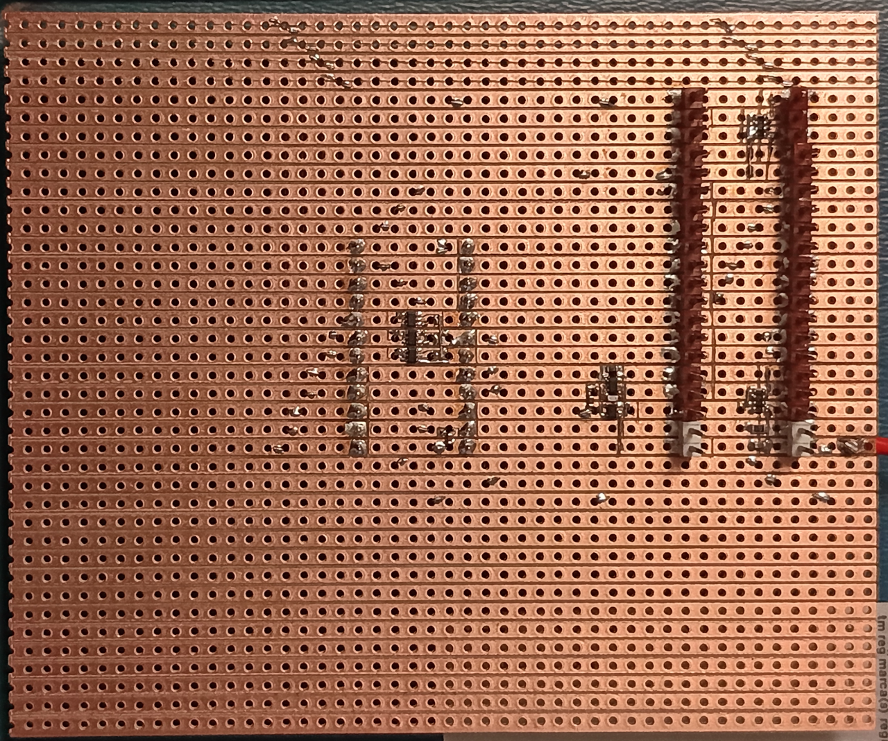 This is the RC oscillator. Same circuit as in the self test card.
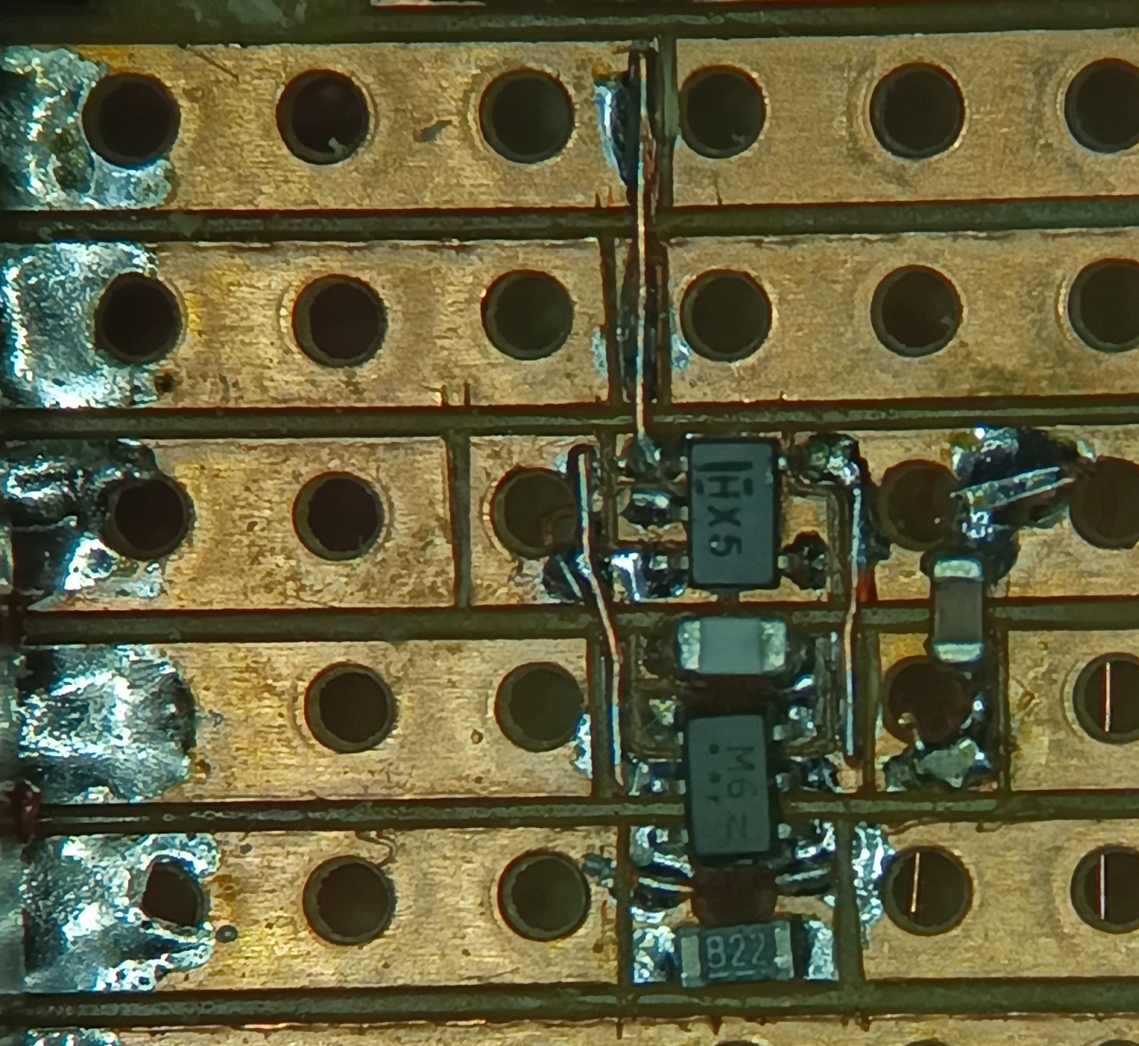 The address FFs are also singles:
 The target board after fixing the ZIF lever issue:
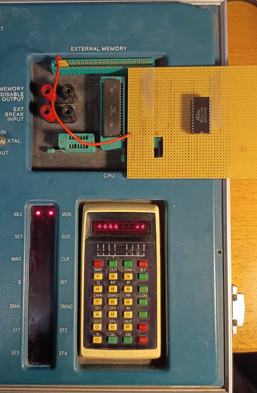
To test the memory board, I first checked with memory reads and writes that some addresses work correctly, writing a few locations with some random bytes and then checking that they held the values.
The next test was to write at the beginning of each 256-byte page a distinct byte, values were 0x11, 0x22, etc. Those also worked fine.
The next test was to enter a small program that fills one page with bytes 0x00...0xFF. The program was as follows:
| Address | Instruction | Bytes | Comment |
| 0x00 | SEP 0 | D0 | P <- 0 |
| 0x01 | SEX 1 | E1 | X <- 1 |
| 0x02 | LDI 0x40 | F8 40 | D <- 0x40 |
| 0x04 | PLO 1 | A1 | R(1).lo <- D |
| 0x05 | LDI 0x00 | F8 00 | D <- 0x00 |
| 0x07 | PHI 1 | B1 | R(1).hi <- D, R1 now point to 0x0040 |
| 0x08 | STR 1 | 51 | *R(1) <- D |
| 0x09 | INC 1 | 11 | R(1) <- R(1) + 1 |
| 0x0A | ADI 1 | FC 01 | D <- D + 1, DF <- overflow |
| 0x0C | BNF 0x08 | 3B 08 | if DF == 0 goto address 0x08 |
| 0x0E | BDF 0x0E | 33 0E | if DF != 0 goto address 0x0E (infinite loop) |
After executing this program I checked the address range 0x0040...0x013F for the values 0x00...0xFF. All was OK.
So, with this card I have a primitive computer with a CPU and 2 kB of memory.
The next step is to check the serial port and see if the debugger can be used from the external console.
Discussions
Become a Hackaday.io Member
Create an account to leave a comment. Already have an account? Log In.