 mircemk


A back-loaded horn speaker is a loudspeaker design that channels the rear sound wave of a driver through a folded horn inside the cabinet to amplify bass efficiently and reduce distortion.
Unlike standard boxes, a back-loaded horn utilizes a complex, winding internal pathway that expands gradually like a musical instrument. The sound waves radiating from the back of the speaker cone travel through expanding channel (the horn), which acoustically amplifies the lower frequencies.
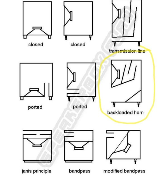
By the time the sound exits the mouth of the horn, it reinforces the bass response, delivering a surprisingly warm, full, and rich sound from a single, full-range driver without the need for a separate subwoofer or crossover network. In this project, we are taking a legendary design concept from Fostex—originally built for massive 8-inch drivers—and scaling it down into a miniature desktop masterpiece. We will be housing a cheap tiny 2-inch full-range driver inside a micro-horn chassis crafted from 5mm PVC material. Driver costs about 2$.
And right from the start, I want to emphasize that this is not a true Hi-Fi quality speaker, but simply a small experiment with which I wanted to test the characteristics and efficiency of this type of speaker box. At the very beginning, I studied the method of designing this type of box, which, by the way, despite the many software for that purpose, is still quite complex and requires a lot of work and testing. When designing, it is necessary to know the basic characteristics of the driver, among which the most basic are the Resonant Frequency and Thele Small parameters given by the manufacturer.
This project is sponsored by PCBWay. Don't forget to visit the PCBWay Open Source Community where you will find countless useful projects divided into different categories. Choose your area of interest where you will find many useful and free projects. You can here also download Gerber files or order ready-made PCBs for some of your future projects. PCBWay has all the services you need to create your project at the best price.
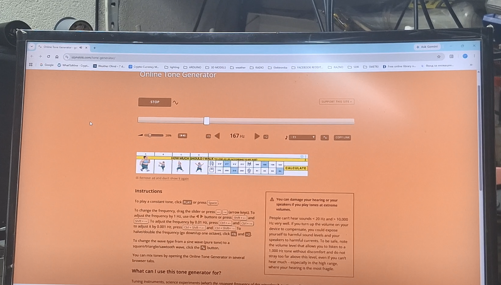
Of course, there is simply no data for this small, cheap driver. At home, without using expensive instruments, we can measure the resonant frequency with great precision, and that is the basic data for making any type of sound box. We need a computer or phone with an audio frequency generator application, an audio amplifier, a resistor with a value of about 10 to 47 Ohms, and a digital multimeter.
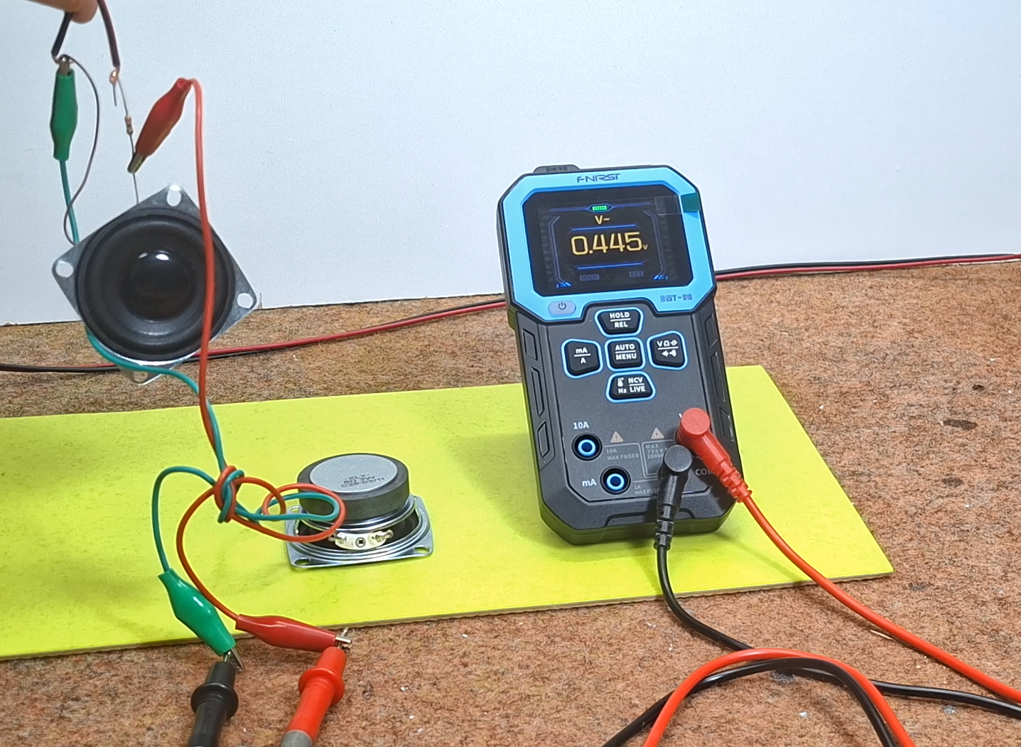
I will use online ton generator. I connect the output of the amplifier through a series resistor to the speaker. Then I connect the multimeter directly to the speaker terminals and let the speaker hang freely in the air so that there is no influence from the environment. Now I gradually change the frequency from 40Hz and up. As the frequency increases, the voltage changes, and when it reaches its maximum value, we read the resonant frequency of the speaker. For this speaker in particular, it is about 170Hz.
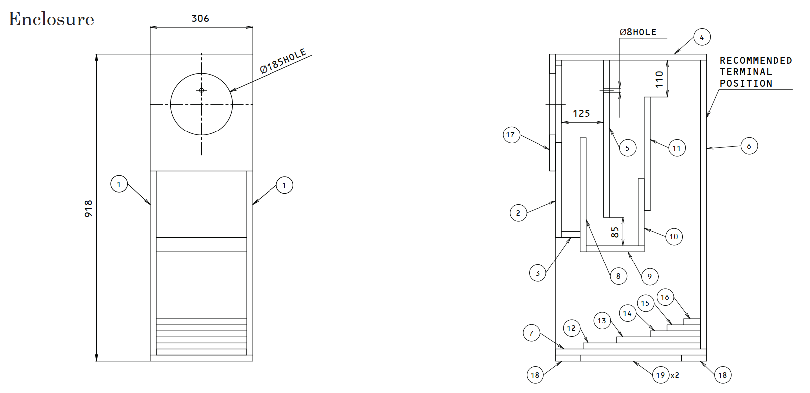
This is the sound box in the construction phase where the sound path from the driver to the exit (mouth) can best be seen.
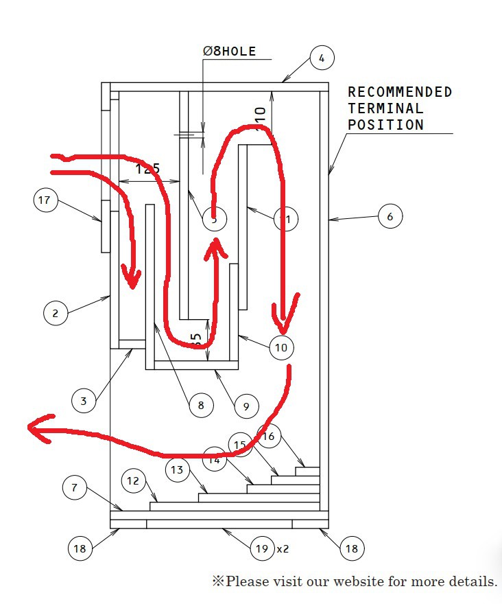
Immediately behind the driver where the sound is generated, there is the first chamber which represents a semi-open sound box in which a damping material is placed. Then the sound continues through a channel which expands exponentially and whose dimensions depend mostly on the resonant frequency of the driver. It should be known that proportional reduction of dimensions does not work like with classic boxes where you can simply reduce the volume proportionally. However, in this specific case, with rough calculations, I came to the result that the resonant frequency of this box is approximately equal to the one I measured for the driver. This was much simpler for me than designing a completely new box with minimally better results.
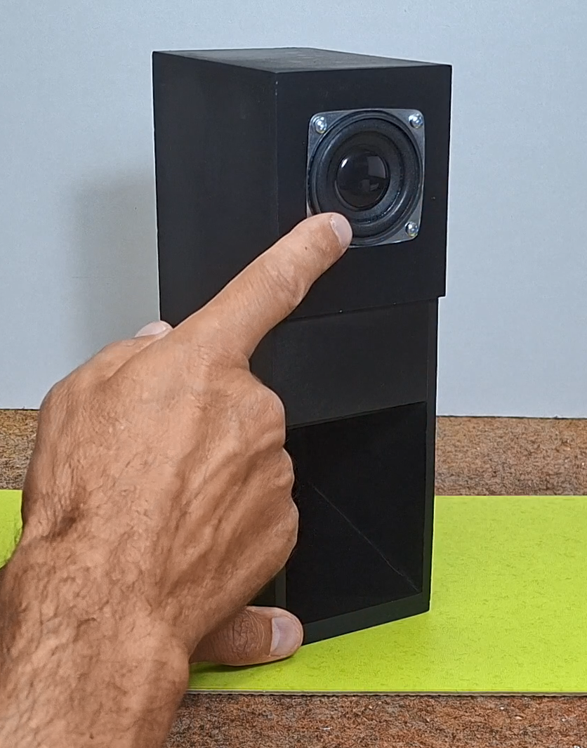
Next comes the most interesting part, which is testing the characteristics...
Read more »


 Sam Pullman
