 Vladimir Tsibrov
Building the keyboard was one of the trickiest parts of the project: tracing the PCB, fabricating it, soldering, and applying symbols to the keys. But one thing at a time.
Since I was crazy enough to aim for a laptop, I needed a full QWERTY keyboard. I settled on a character set — 64 keys in total, which fits neatly into an 8×8 matrix, requiring two 8-bit ports from the microcontroller (fortunately, free ports are not in short supply on the ATmega2560). But in reality the keys were arranged in an 11×6 rectangle, which made routing less than convenient. I did the schematic and layout in the online editor EasyEDA. Then came milling the board on a CNC3018 and soldering the switches (this was my first attempt at making a double-sided board with UV-curable solder mask, so not everything went perfectly).
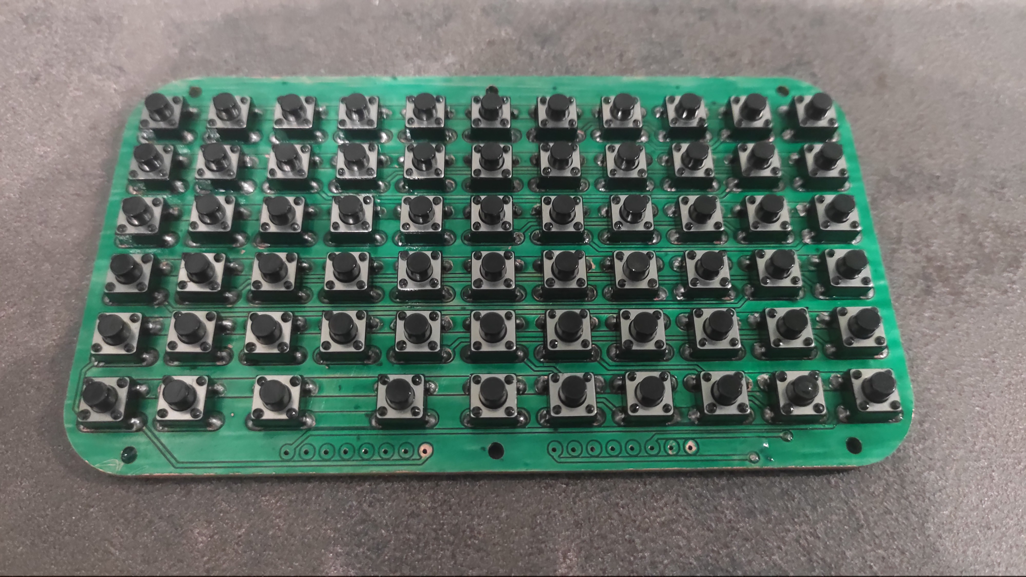
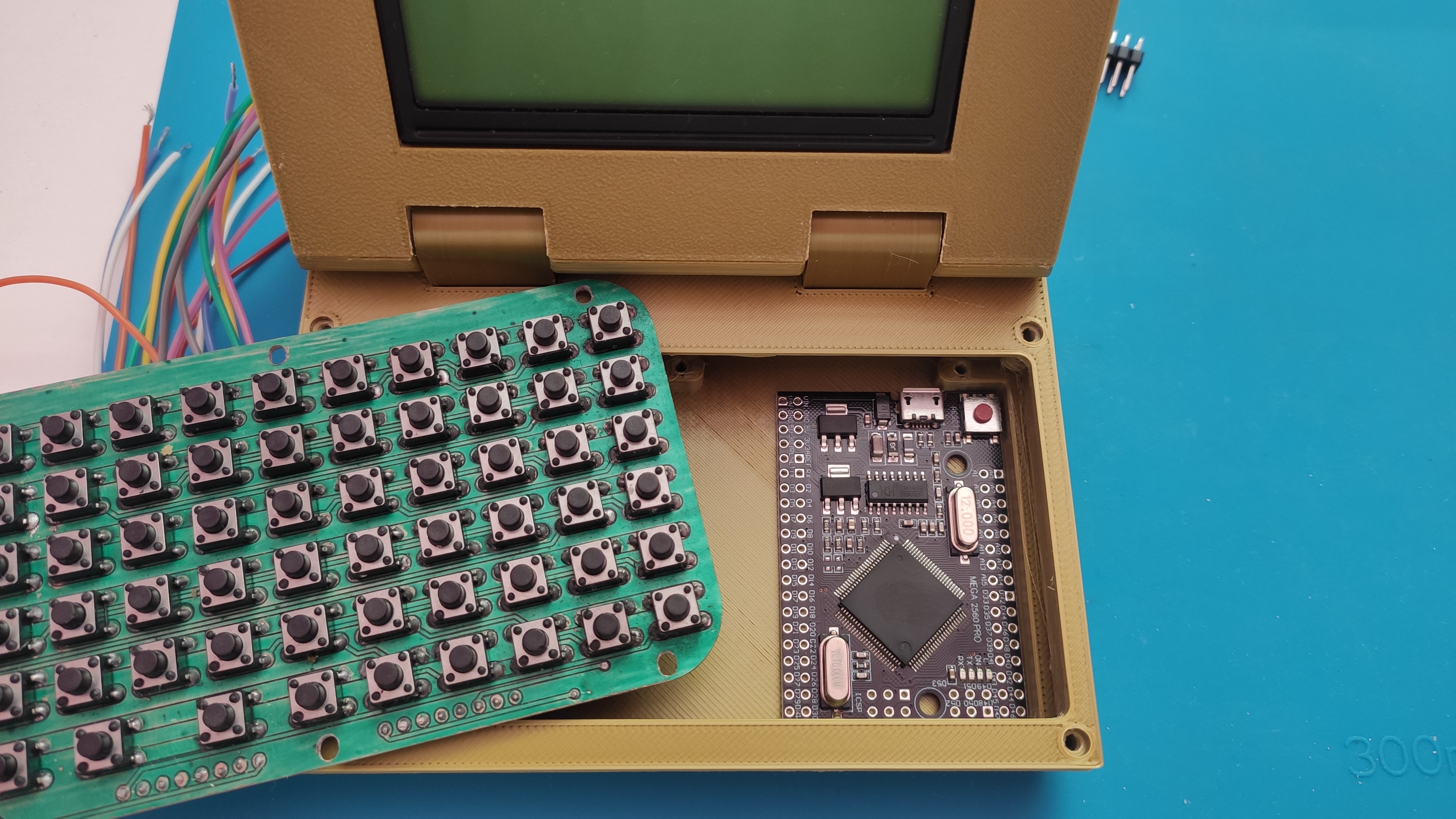
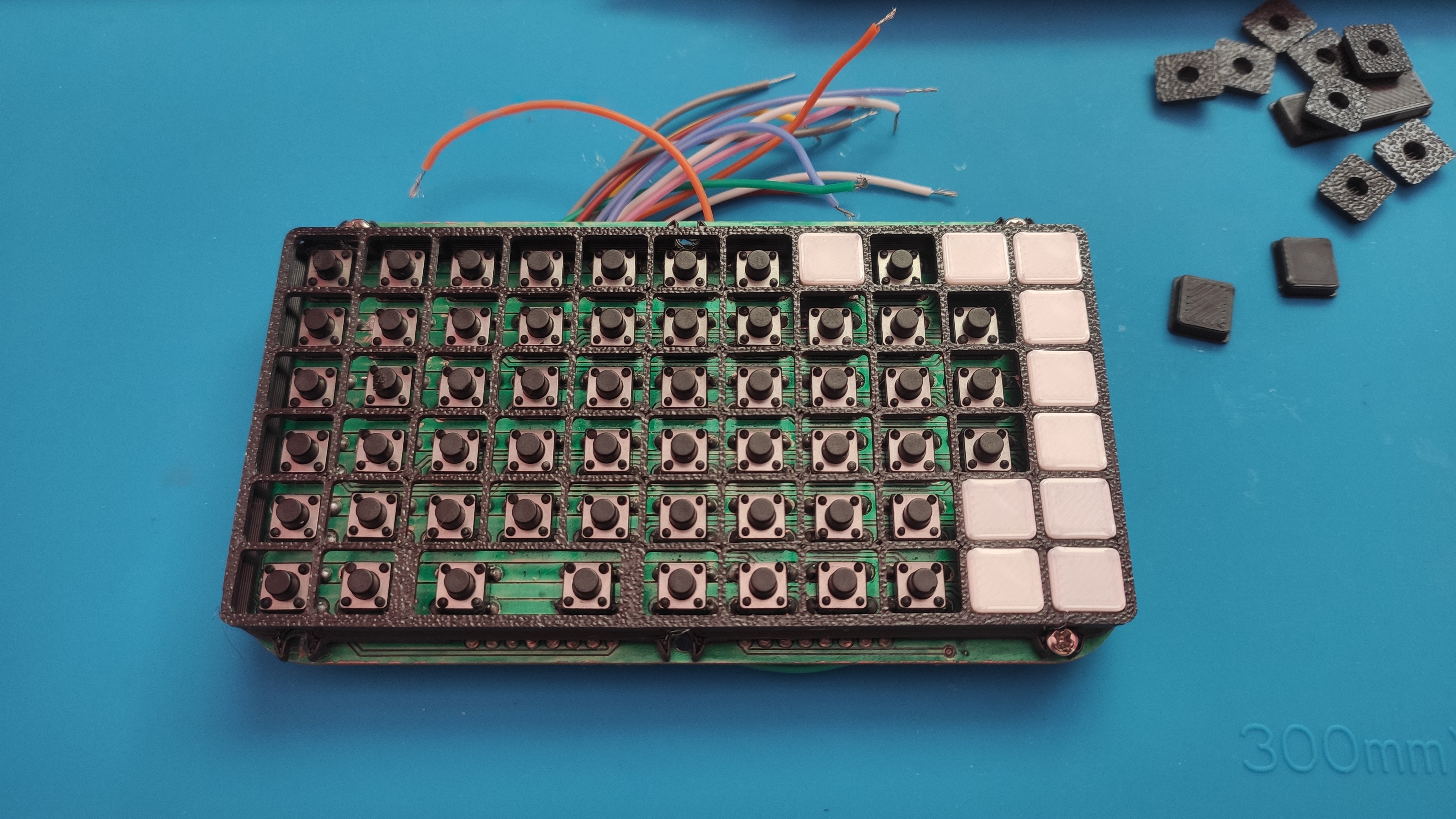
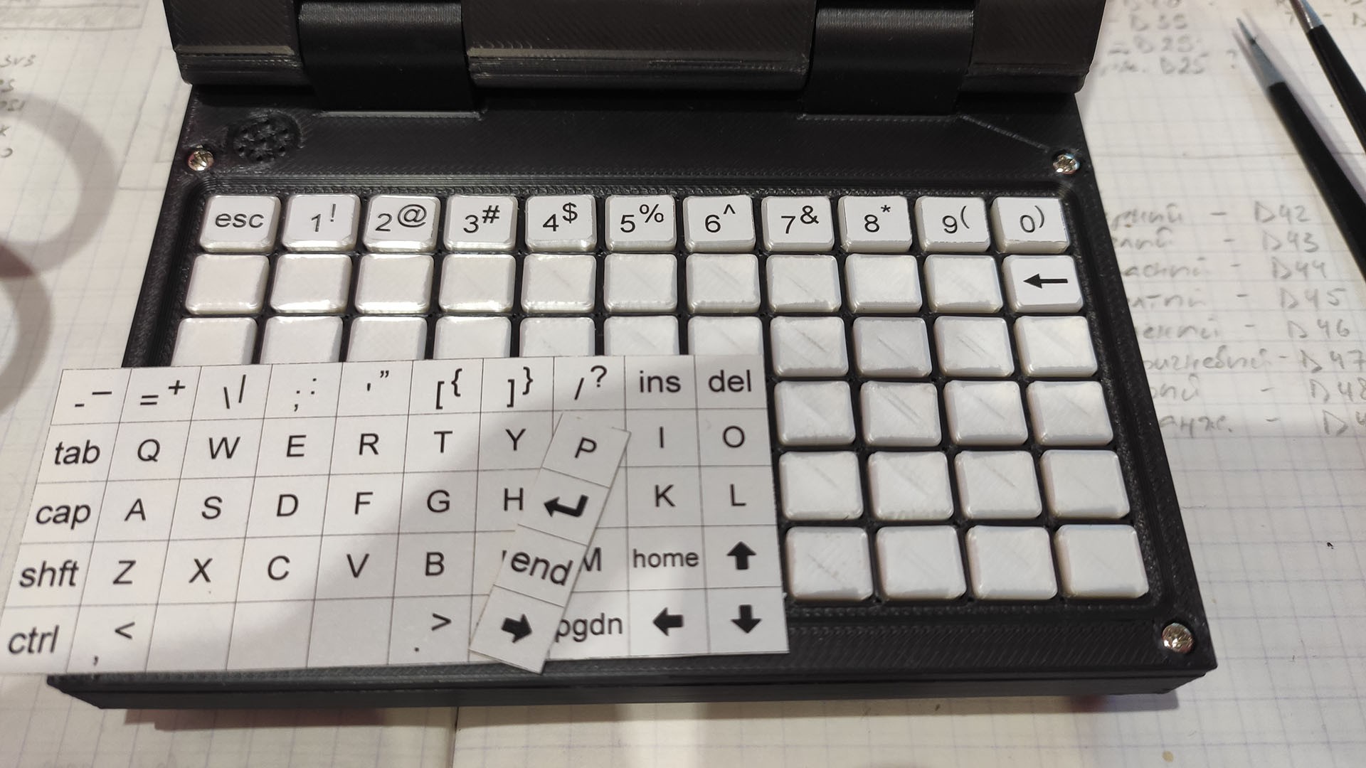
Originally I had the idea of making the keyboard with keycaps as a single solid module, but I later abandoned it. As for the key labeling — I printed the symbols on sticker paper, cut them out, and glued them on.
Scanning the keyboard is the classic matrix approach. The microcontroller activates each column of the matrix in turn, pulling it low, and while that column is active it reads the state of the rows. If a key in the current column is pressed, the corresponding row gets pulled low — that's how the press coordinate is determined. Scanning runs continuously, column by column, at a rate of hundreds of hertz — standard practice for matrix keyboards. I added debouncing in software: a key's state is only confirmed after several consecutive scans with an unchanged value, which filters out false triggers.
Later I decided to rework the keyboard: add a diode to each key for more reliable detection of key combinations, and also switch column selection to a 4-to-16 decoder. Now four pins are enough to select a column, and there's headroom to expand the keyboard to 16 columns; there's room on the rows too — currently there are 6, but reading a whole microcontroller port makes it easy to bump that up to 8 — might come in handy in future versions of the project. This time the keyboard came out single-sided and very tidy. The decoder went on a separate board. And for future versions I'm planning to use SMD switches and put the decoder and a dedicated microcontroller for key scanning on the back side.
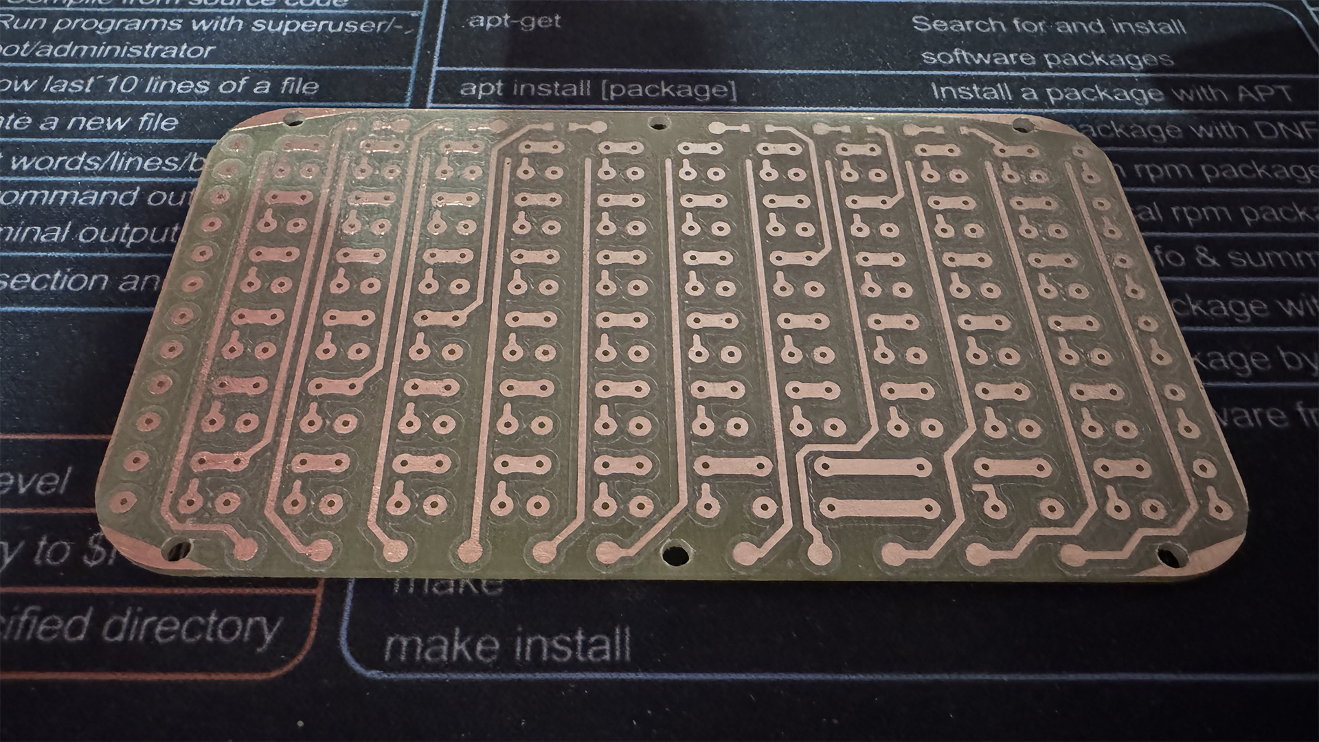
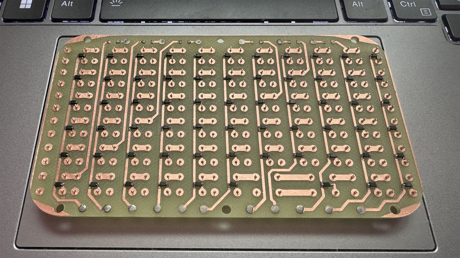
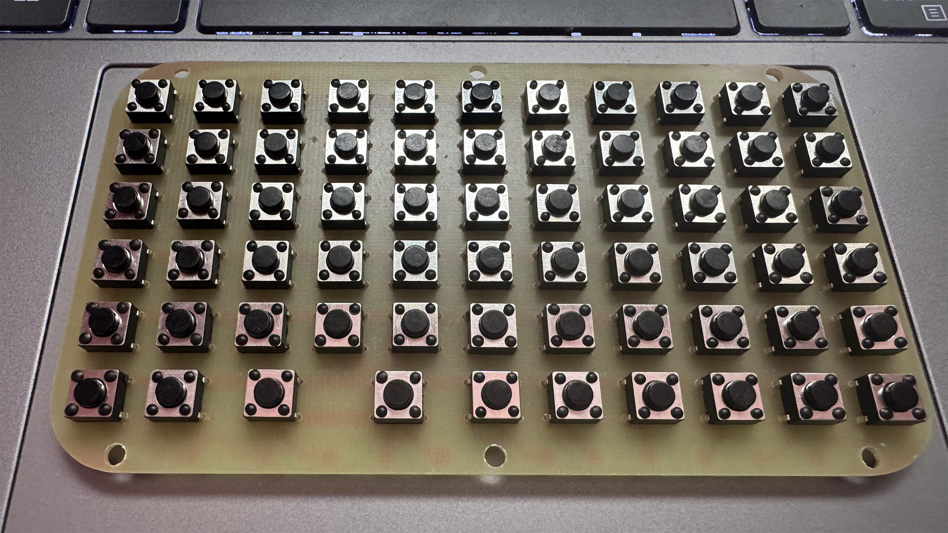
Over time the stickers started peeling off on the most-used keys. So I started looking for a new way to apply the labeling. I experimented with different methods: printing symbols with a 0.25 mm nozzle, burning away paint with a laser, exposing UV-curable solder mask through a negative mask, and toner transfer with solvent and pressure. In the end I settled on the method described here: https://hackaday.com/2025/01/02/dress-up-your-3d-prints-with-toner-transfer-labels
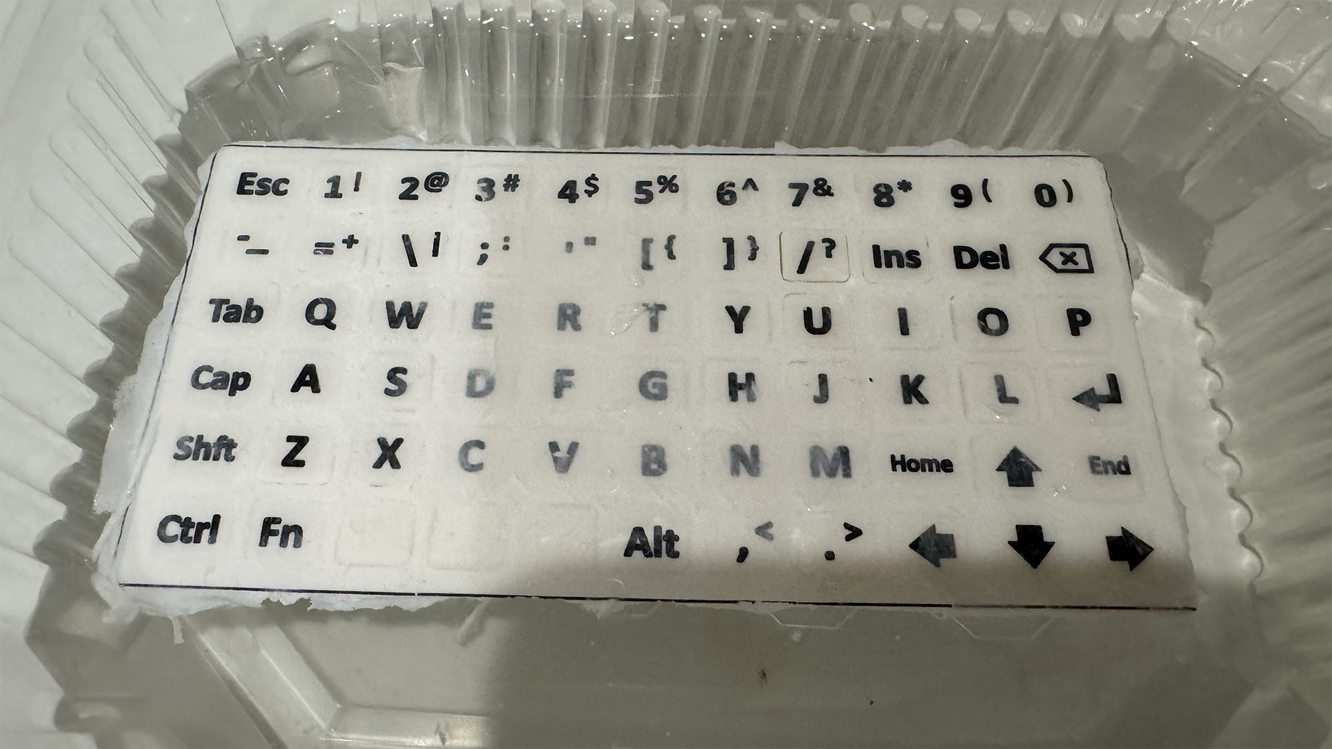
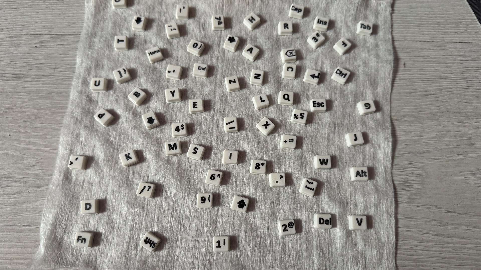
The labeling came out crisp and durable. I'm planning to add a protective coating (probably clear lacquer — need to experiment), to protect the symbols from wearing off.
Discussions
Become a Hackaday.io Member
Create an account to leave a comment. Already have an account? Log In.