 Quinn
QuinnTo sort out what modifications were needed to this, I did some exploration of the RE-650 Video Visualizer. Here are some pictures:
Camera removed:
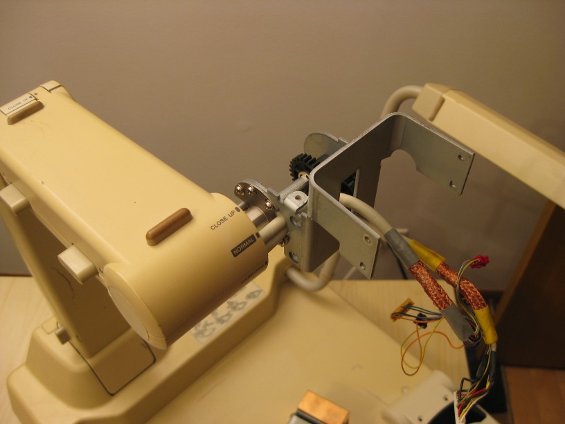
With the camera removed, we are left with a sturdy metal bracket I should be able to modify, and the original wiring that snakes through the arm. I'll likely replace the wiring with my own.
Original camera:
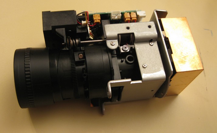
The original camera has a zoom lens, motorized control of both the zoom and focus, and a reflective autofocus system. While it is unlabeled, the lens is not a long enough focal length to work as a microscope, so I cannot use this simply by changing the sensor. It has a removable macro lens attachment which fits some of the other lenses I have, which is an option to consider. I might try to re-use the motors and motor controls on the lens I chose previously, but we'll see.
Under the base:

There is a surprising amount of electronics under here, which I think mostly reflects it's age. I couldn't find an age, but I expect it to be 1990's vintage.
At far left is a modular 9VDC output power supply.
Lower center is the driver for the two florescent lamps. This takes in 9VDC and only has a 2 pin connection to the main board.
The main board in the center appears to do most of the camera management to take the image sensor output and create the NTSC video output.
Upper center is a mux board, which switches between the camera video, and the two external video inputs. It also has a microphone amplifier, and muxes it with the two external audio inputs.
The two boards on the right are the user panel I/O.(the top cover is flipped over to the right, so you are seeing the bottom side with the slide out handle) These are nicely independent circuits, with built on pull ups for the buttons, a divider circuit for the potentiometer, and a open collector driver chip to drive the LEDs. The connections are parallel, one line for each button, and each LED.(except power, which is driven from the 5V rail without control.
I don't think I'll do much circuitry modifications except for tying into the I/O boards. I will probably just leave the rest of the circuits as-is, even though much of it I won't be using.
Discussions
Become a Hackaday.io Member
Create an account to leave a comment. Already have an account? Log In.